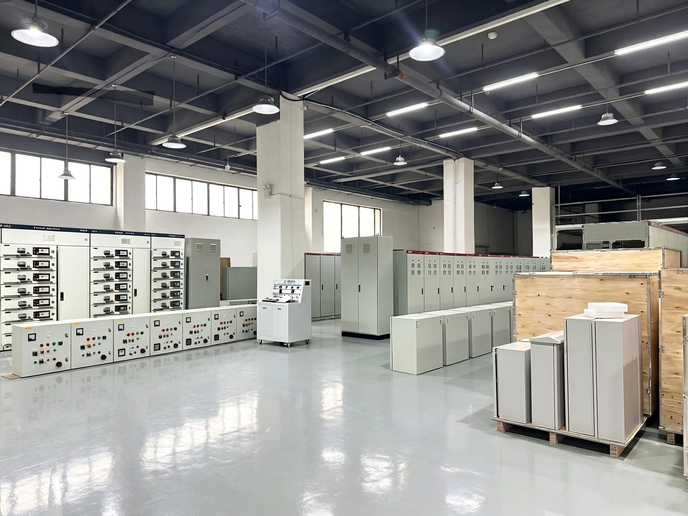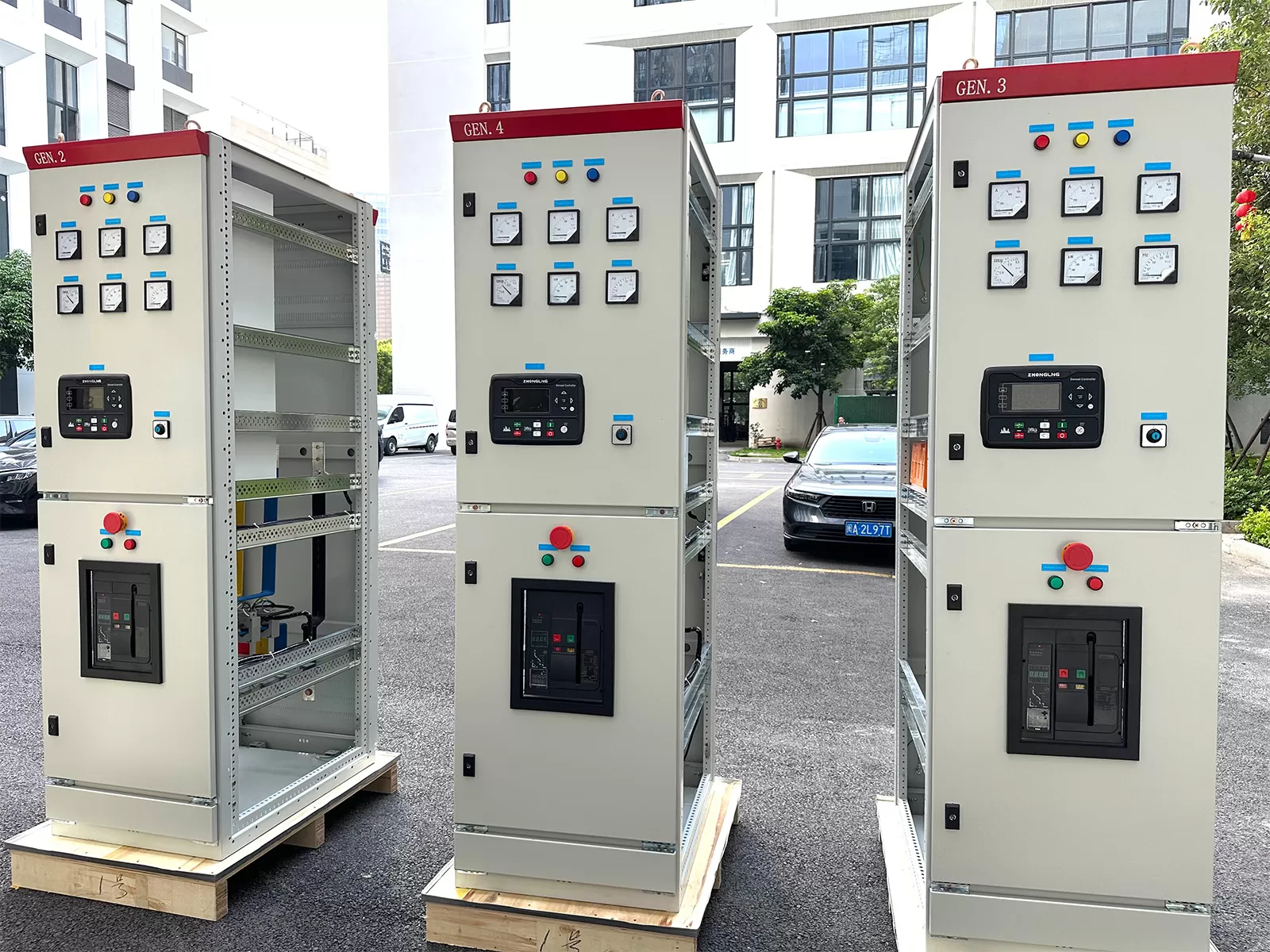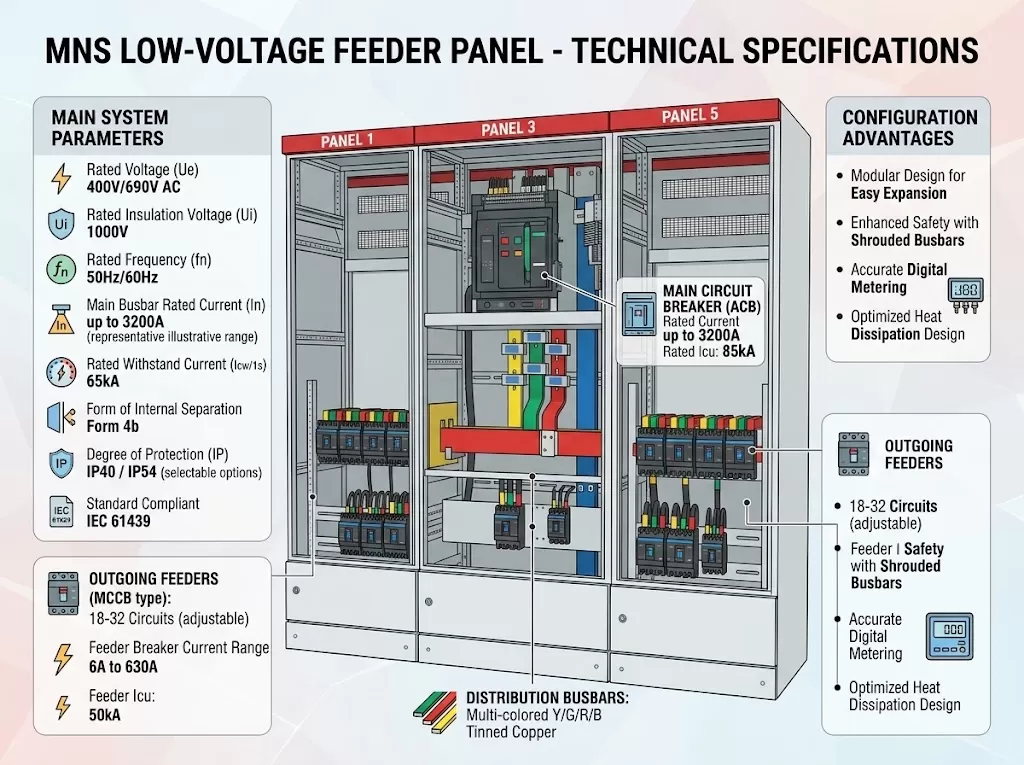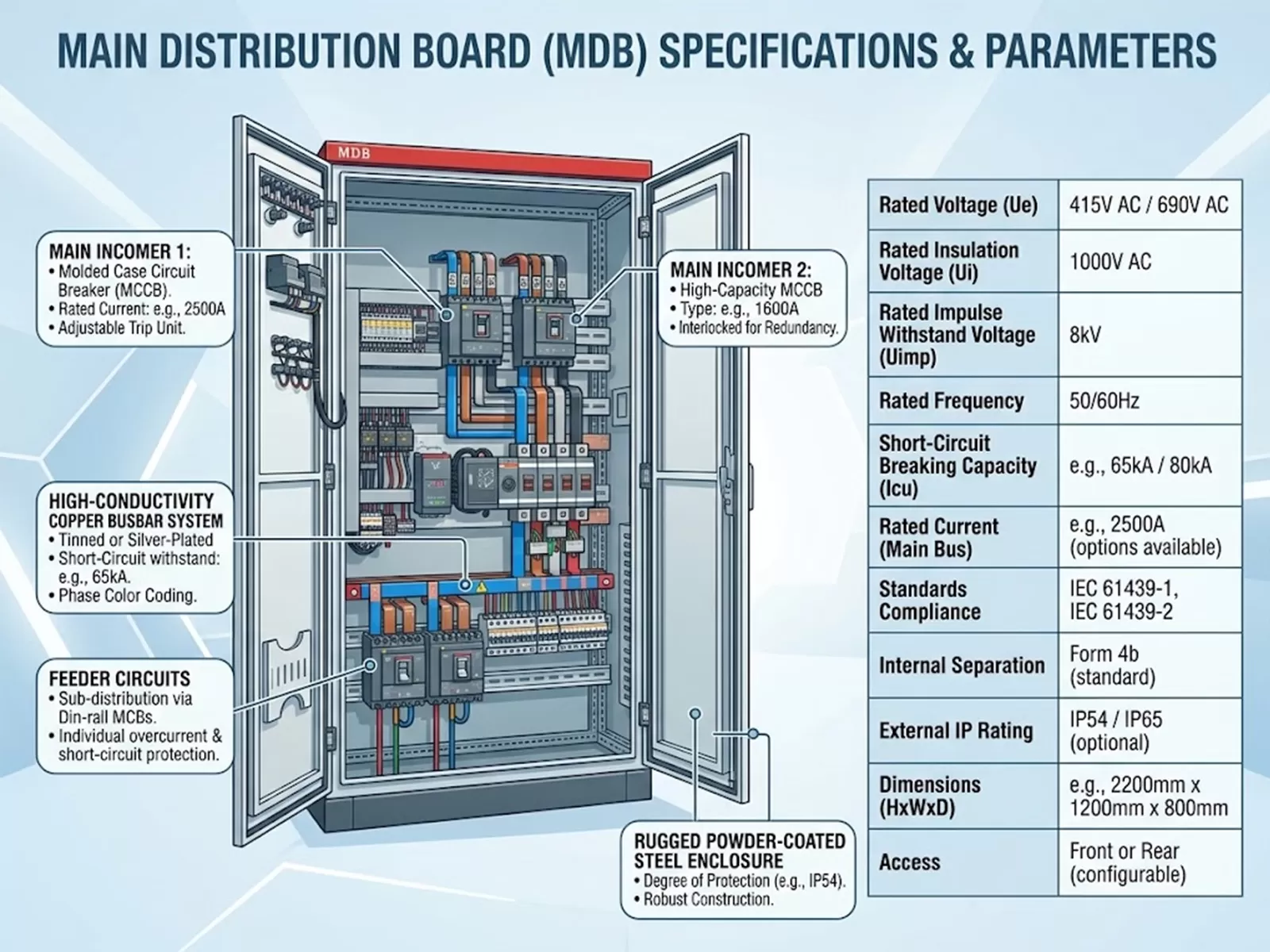
Modern electrical automation within advanced manufacturing environments requires an uncompromising approach to power continuity, equipment safety, and operational efficiency. Automated assembly lines, multi-axis robotics, and continuous process plants impose non-linear electrical stresses that legacy infrastructure cannot handle. At the center of this power ecosystem lies the distribution board, functioning not merely as an enclosure housing circuit protective devices, but as an engineered node that governs power quality, sub-circuit isolation, and fault containment across dynamic production floors.
Specifying electrical distribution infrastructure for precision manufacturing demands rigorous alignment between mechanical layout, thermal performance, fault tolerance, and communication topology. As automated systems integrate increasingly complex variable frequency drives (VFDs), servo systems, and programmable logic controllers (PLCs), the incoming power architecture must mitigate harmonic distortion, withstand high prospective short-circuit currents, and prevent cascading downtime. Achieving these parameters requires an exhaustive evaluation of international standards, component coordination, and structural enclosure design.
.webp?t=1789874639335 "distribution board")
Technical Architecture and Form Separation in Industrial Environments
Specifying low-voltage assemblies for automated manufacturing centers around the internal separation of functional units, busbars, and terminals. International standard IEC 61439-2 defines these configurations to protect personnel against contact with live internal parts and prevent internal arc faults from migrating across adjacent compartments.
Form 1: Offers no internal separation; busbars, operational switches, and output terminals share a common compartment. This configuration is unsuitable for mission-critical automation facilities due to maintenance risks and vulnerability to widespread fault propagation.
Form 2 (2a and 2b): Separates the main horizontal and vertical busbars from the functional units. In Form 2b configurations, the connection terminals are also segregated from the busbars, providing basic physical safety during sub-circuit cable inspection without de-energizing the main bus system.
Form 3 (3a and 3b): Isolates functional units from one another as well as from the primary busbars. In Form 3b, outgoing connection terminals remain separated from the functional units and are grouped into dedicated external termination areas, preventing localized component failures from degrading nearby equipment.
Form 4 (4a and 4b): Represents the benchmark standard for high-reliability manufacturing equipment. Form 4b isolates individual functional units from each other, keeps them distinct from the busbar network, and establishes segregated terminal compartments for each circuit. This arrangement permits maintenance technicians to terminate or modify field cabling on an isolated circuit while neighboring drives, automation cells, and machinery continue operating under full power.
Within high-capacity manufacturing cells, short-circuit withstand capacity ($I_{cw}$) determines the mechanical integrity of the internal copper busbar network during upstream electromagnetic faults. Electromechanical forces generated during peak short-circuit occurrences ($I_{pk}$) exert substantial mechanical strain on busbar supports. Glass-fiber reinforced polyester insulating brackets must be positioned along the main and dropper bus run with span calculations verified to resist lateral deflection and thermal warping during sub-transient fault phases.
Harmonics, Power Quality, and Protection Coordination
Automated manufacturing facilities deploy dense arrays of three-phase power electronics, including regenerative drive systems, switched-mode DC power supplies, and high-frequency induction heaters. These non-linear loads inject significant harmonic currents—predominantly the 5th, 7th, 11th, and 13th orders—into local sub-distribution networks. This harmonic presence increases technical demands placed on the primary distribution board serving automated production machinery.
Triplen harmonics (3rd, 9th, 15th) present in single-phase automated testing arrays accumulate additively within the neutral conductor, frequently causing neutral phase currents to exceed nominal line currents. Engineering specifications must account for this by deploying full-size or double-size neutral busbars and neutral-disconnect switches. Derating calculations must be applied to active conductors based on the calculated Total Harmonic Distortion for Current ($THD_i$), ensuring operational temperatures do not degrade insulation polymers or accelerate terminal oxidation.
Achieving total selective coordination (discrimination) between incoming Air Circuit Breakers (ACBs), intermediate Molded Case Circuit Breakers (MCCBs), and branch Miniature Circuit Breakers (MCBs) prevents localized equipment faults from shutting down entire production cells. Engineers rely on time-current curves and energy-based discrimination principles:
Overload Discrimination: Achieved through thermal-magnetic or electronic trip units configured to ensure the downstream branch protective device clears long-duration minor overcurrents before the upstream breaker begins timing out.
Short-Circuit Discrimination: Relies on the prospective fault level ($I_{k}$) and short-time withstand ratings ($I_{cw}$). Electronic trip units utilizing $I^2t$ shaping profiles introduce calibrated millisecond delays on upstream breakers, allowing downstream devices to isolate the affected branch while maintaining voltage stability to adjacent automation modules.
Current-Limiting Characteristics: Ultra-fast downstream limiting breakers restrict let-through energy ($I^2t$), extinguishing short circuits within the first quarter-cycle to prevent electromagnetic shock from transferring upstream to vulnerable PLC control panels.
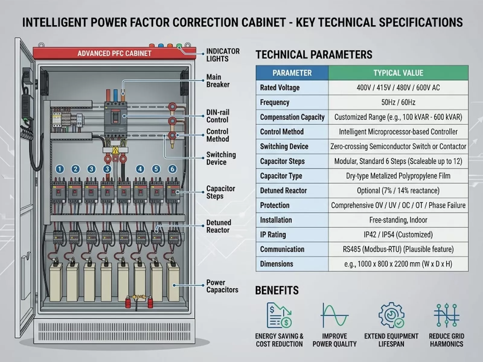
Engineering teams frequently integrate active harmonic filters (AHFs) or static var compensators (SVCs) directly into incoming distribution lineups. Engineering teams at XDEPE collaborate with industrial designers to configure custom enclosures that integrate passive detuned reactor banks and active harmonic suppression hardware into the switchgear assembly, mitigating power disturbances before they reach sensitive servo controllers.
Thermal Dynamics and Enclosure Engineering
Heat dissipation represents a persistent design challenge inside modern distribution assemblies. With automated plants demanding high component density inside compact floor spaces, the cumulative thermal losses generated by internal breaker mechanisms, contact resistances, terminal lugs, and active components can rapidly escalate the internal temperature beyond safe component operational envelopes.
Thermal management calculations rely on baseline Joulean dissipation models ($P_{loss} = I^2 R$). As ambient temperatures rise inside unconditioned factory environments, operational derating must be applied to switchgear ratings based on IEC 60947 series standards. An MCCB rated for 250A at a nominal 40°C calibration benchmark exhibits reduced continuous ampacity when internal ambient temperatures reach 55°C or 60°C, precipitating nuisance tripping if enclosure ventilation fails.
Natural Convection vs. Forced Air Systems: Enclosures relying on natural buoyancy require precise baffle placement, intake filter locations near the plinth, and top-mounted louvered exhaust canopies. High-density automation layouts typically mandate forced-air cooling equipped with thermostatically controlled blower modules, differential pressure sensors, and easily replaceable particulate filters.
Ingress Protection Trade-Offs: Industrial environments laden with cutting fluid aerosols, metallic dust, or airborne moisture require enclosures conforming to IP54, IP55, or IP65 ratings. Higher ingress ratings impede heat transfer through natural air exchange, requiring closed-loop heat exchangers, thermoelectric coolers, or integrated air-conditioning units mounted on the enclosure walls to isolate internal electronics from environmental contaminants.
Internal Arc Fault Containment: Modern distribution board safety paradigms incorporate arc flash containment topologies governed by IEC/TR 61641. Assemblies engineered with arc-resistant ducting, internal pressure relief flaps, and phase barriers direct superheated gases upward through dedicated exhaust chimneys, preserving operator safety and preventing collateral damage to neighboring machine control panels during catastrophic internal failure events.
Smart Distribution Architectures for Automated Manufacturing
The convergence of power engineering and operational technology has transformed the distribution board from a static hardware enclosure into a dynamic data node within Industry 4.0 architectures. Automated facilities require granular visibility into power parameters to detect motor degradation, forecast equipment wear, and avoid peak demand penalties.
Modern switchboards integrate intelligent electronic devices (IEDs), Rogowski coil current sensors, and micro-electromechanical systems (MEMS) temperature sensors directly onto critical connection points:
Continuous Busbar Temperature Monitoring: Infrared thermal sensors or non-conductive fiber-optic surface probes monitor main busbar splices, cable termination lugs, and breaker finger clusters. Detecting micro-ohm resistance increases allows maintenance personnel to address loose terminations or surface oxidation long before thermal runaway triggers an unplanned outage.
High-Speed Digital Communications: Field devices collect phase voltages, current wave shapes, power factor, and individual harmonic spectrums up to the 63rd order. Embedded industrial gateway units translate internal fieldbus communications (e.g., Modbus RTU) into deterministic automation protocols such as PROFINET, EtherNet/IP, or OPC UA, transferring continuous diagnostic streams directly to supervisory SCADA systems and distributed control systems (DCS).
Predictive Contact Wear Analytics: Modern digital trip units compute breaker contact degradation based on historical interruption counts, breaking currents, and ambient mechanical operations. Facilities can transition from rigid periodic teardown schedules to predictive maintenance workflows driven by actual operational telemetry.
Specialized systems engineered by XDEPE incorporate integrated digital gateways and power monitoring frameworks, providing modular field-connection flexibility that simplifies system expansion when manufacturing lines undergo retooling or capacity expansions.
Engineering Procurement Criteria for Automation Applications
Selecting and commissioning power distribution gear within automated process facilities requires balancing initial capital expenditure against long-term operational resilience. Engineering teams, project procurement managers, and systems integrators must establish technical specifications that eliminate vulnerabilities early in the design phase.
The primary consideration involves verifying certified compliance with the IEC 61439-1 and IEC 61439-2 product standards. Procurement checklists should require comprehensive Type Test Certificates verifying the following baseline design rules:
Temperature Rise Limits: Independent test evidence demonstrating that continuous full-load operational conditions will not exceed allowable thermal limits on busbars, terminals, and external enclosure covers.
Dielectric Properties: Verification of rated impulse withstand voltage ($U_{imp}$) performance, confirming the assembly can withstand high-voltage switching transients generated by heavy inductive motor loads without insulation puncture.
Short-Circuit Withstand Validation: Dynamic and thermal tests demonstrating the busbar matrix and feeder breakers maintain physical integrity during calculated prospective fault currents without phase flashover.
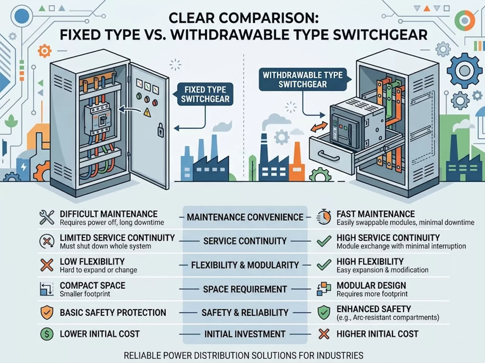
Mechanical Operation: Verified mechanical durability of drawout racks, safety shutters, and interlock systems through thousands of non-powered operational cycles.
Customization capabilities play a substantial role when matching distribution equipment to automated machinery footprints. Space-constrained cleanrooms, automotive stamping bays, and electronics fabrication facilities require custom spatial profiles, top or bottom cable entry variations, and pre-engineered seismic bracing. Through active design collaboration, XDEPE assists plant engineers in designing specialized, form-separated configurations that integrate physical constraints with precise power distribution profiles.
.webp?t=1789874639335 "distribution board")
Operational Maintenance, Commissioning, and Testing
Ensuring the operational longevity of a heavy-duty distribution board requires disciplined commissioning and ongoing lifecycle maintenance protocols. Once installed in an industrial plant, field assemblies face continuous vibration, harmonic heating, and atmospheric fluctuations that require structured surveillance.
Site Acceptance Testing (SAT) establishes the baseline operational profile of the equipment prior to energization. Comprehensive SAT procedures include high-potential (Hi-Pot) dielectric testing, micro-ohmmeter contact resistance measurements across all bolted busbar joints (typically targeting values below 50 micro-ohms per junction), and primary/secondary current injection testing to calibrate protective relay trip thresholds.
During ongoing plant operations, maintenance frameworks leverage non-invasive condition monitoring alongside scheduled mechanical inspections:
Periodic Thermographic Audits: Conducting periodic infrared thermography under maximum plant operating load conditions highlights anomalous heat signatures caused by loose torque tolerances, localized phase imbalances, or component internal wear.
Torque Verification Schedules: Mechanically fastened connections experience micro-settling under continuous cyclic thermal loading. Maintenance guidelines specify periodic torque audits using calibrated digital torque tools against manufacturer-specified clamping specifications.
Insulation Resistance Profiling: Routine megohmmeter testing ($1000\text{V DC}$) tracks gradual dielectric breakdown caused by dust accumulation, atmospheric moisture, or chemical vapor exposure across phase-to-phase and phase-to-ground barriers over multi-year periods.
Frequently Asked Questions
Q1: What is the primary operational difference between Form 3b and
Form 4b internal separation?
A1: In Form 3b assemblies, the
functional units are isolated from each other and from the busbars, but their
outgoing connection terminals reside in a shared terminal compartment. In Form
4b assemblies, the outgoing terminals for each functional unit are physically
segregated into individual, self-contained terminal compartments. Form 4b allows
maintenance personnel to safely wire, inspect, or adjust terminations for a
single isolated circuit without exposing themselves to adjacent operational
circuits.
Q2: Why must the prospective short-circuit rating ($I_{cu}$) be
evaluated alongside service breaking capacity ($I_{cs}$)?
A2: The
rated ultimate short-circuit breaking capacity ($I_{cu}$) defines the maximum
fault current an overcurrent device can break safely, though the breaker may
sustain severe contact erosion and require immediate replacement afterward. The
rated service short-circuit breaking capacity ($I_{cs}$) defines the fault
current level the device can interrupt repeatedly while remaining fully
operational. For critical automation plants where rapid power restoration is
mandatory, procurement specifications should target equipment where $I_{cs} =
100\% \ I_{cu}$.
Q3: How do variable frequency drives influence the thermal rating of
an incoming distribution board?
A3: Variable frequency drives draw
non-sinusoidal currents rich in odd harmonics, which induce additional
eddy-current and skin-effect losses within copper conductors, transformer
secondaries, and breaker trip units. These losses generate excess heat,
requiring engineers to calculate total harmonic loading and apply derating
factors to the busbar system, trip units, and surrounding enclosure
enclosures.
Q4: Under what conditions should an internal arc-resistant design be
mandated?
A4: Arc-resistant design (complying with IEC/TR 61641
criteria) should be mandated in facilities featuring high prospective fault
currents (exceeding 50kA), locations where maintenance staff work in close
proximity to energized panels, or mission-critical process plants where an
internal flashover would result in catastrophic secondary damage and prolonged
facility downtime.
Q5: Can existing distribution board infrastructure be retrofitted to
enable digital energy monitoring?
A5: Yes. Modernization frameworks
routinely integrate split-core current transformers, Rogowski coils, wireless
magnetic temperature nodes, and modular external digital gateways into operating
panels without requiring busbar reconstruction. These components digitize legacy
switchgear, exporting operational data onto plant-wide SCADA and energy
management platforms.
Plan your next automation power infrastructure project with engineered confidence. Contact the engineering design specialists at XDEPE to review your project specifications, obtain comprehensive technical documentation, and configure custom, standards-compliant distribution systems tailored to your facility requirements.
Direct Engineering Inquiries: yoyo@xdepe.com