Introduction
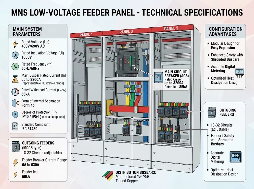
Many factory owners do not realize they are paying a hidden tax on their electricity bills. Utility companies charge heavy penalties for factories with poor power quality. This happens when motors and transformers consume too much reactive energy.
A poorly optimized electrical grid also generates excessive heat. This significantly shortens the lifespan of your expensive facility equipment. It can even cause unexplained tripping in your main circuit breakers.
Integrating a reliable PFC cabinet immediately solves these expensive issues. It acts as an active filter and optimizer for your entire facility.
What is a Power Factor Correction Panel?
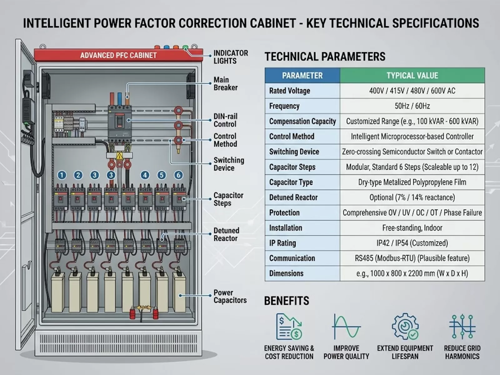
A power factor correction panel is a specialized electrical enclosure designed to improve the efficiency of your electrical grid.
It constantly injects reactive power back into the system to stabilize the load. This ensures your facility uses almost 100% of the electricity it pays for.
Key benefits of installing this equipment include:
Eliminating reactive power penalties from utility providers completely.
Reducing thermal stress on internal cables and facility transformers.
Increasing the available power capacity of your existing low voltage switchgear.
Stabilizing voltage drops during the startup of heavy machinery.
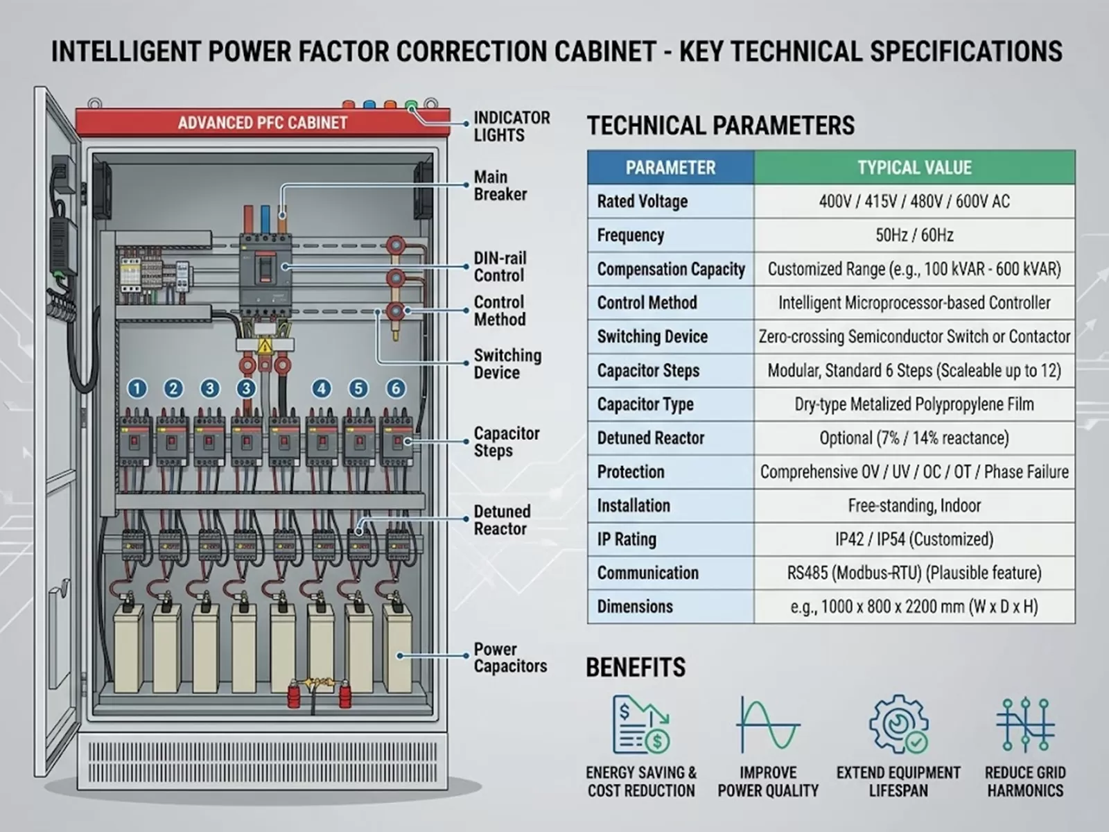
Standard Technical Specifications for PFC Cabinets
| Specification | Standard Industrial Range | Application Note |
| Rated Voltage | 400V / 415V / 480V / 690V | Matches standard global low voltage grids. |
| Compensation Capacity | 100 kVAR to 1200 kVAR | Scalable based on total factory motor loads. |
| Operating Frequency | 50Hz or 60Hz | Must match the specific destination country grid. |
| Enclosure Protection | IP42 (Indoor) / IP54 (Outdoor) | Ensures protection against factory dust and moisture. |
How Does Reactive Power Compensation Work?
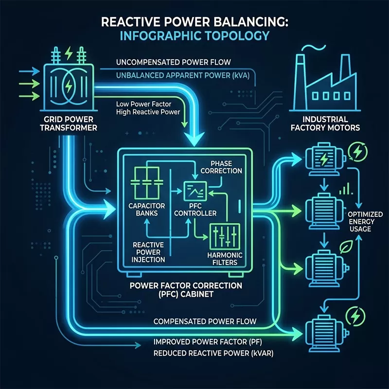
Understanding reactive power compensation is easier than it sounds. Think of it as a smart balancing system for your factory's electrical current.
Here is the exact step-by-step process of how the cabinet operates:
● Step 1 (Monitor): The master controller constantly measures the voltage and current entering the facility.
● Step 2 (Calculate): It calculates the real-time power factor lag caused by running motors or pumps.
● Step 3 (Compensate): The system automatically switches on the exact number of capacitors needed to fix the lag.
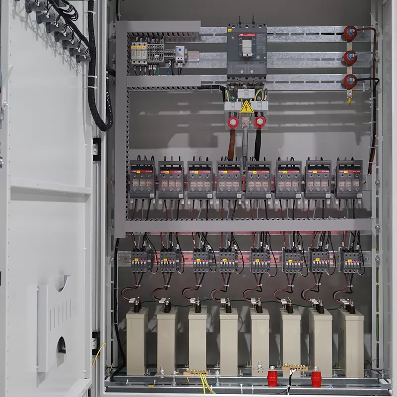
Key Components of a Capacitor Bank Panel
To ensure long-term power quality improvement, the internal components must be premium grade. Here is a breakdown of what sits inside a professional capacitor bank panel.
1. Automatic Power Factor Controller (APFC)
The automatic power factor controller (APFC) is the brain of the entire cabinet. It analyzes grid data in milliseconds to command the switching sequences.
2. Cylindrical Power Capacitors
These act as the actual energy storage units within the system. High-quality dry-type capacitors offer self-healing technology for maximum safety.
3. Detuned Reactors
Harmonic distortion can easily destroy standard capacitors in modern plants. Detuned reactors are heavy copper coils that block these harmful frequencies.
Capacitor Switching Technology Comparison
| Switching Component | Best Use Case | Switching Speed | Lifespan & Wear |
| Magnetic Contactors | Standard manufacturing loads | Moderate (Seconds) | Mechanical wear over time; standard life. |
| Thyristor Switches | Rapidly changing dynamic loads | Ultra-fast (Milliseconds) | Solid-state zero wear; extremely long life. |
Main Types of PFC Systems
Not every facility requires the exact same setup. Engineers typically choose between two main configurations based on the load profile.
Fixed Power Factor Correction
○ Ideal for transformers or large motors that run continuously at a constant load.
○ Provides a static amount of compensation without complex controllers.
○ Lower initial purchase cost and highly simple maintenance.
Automatic Power Factor Correction (APFC)
○ Perfect for modern factories where power loads fluctuate wildly throughout the day.
○ Automatically steps the capacitance up or down to match real-time demand.
○ Prevents dangerous over-compensation during low-load night shifts.
Typical Applications and Industries
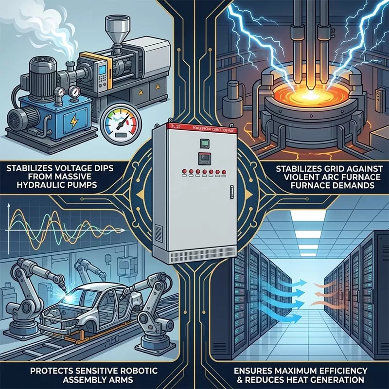
Robust industrial power distribution relies heavily on clean energy. These cabinets are mandatory in facilities utilizing heavy inductive loads.
● Plastic Injection Molding: Prevents voltage dips when massive hydraulic pumps kick on.
● Steel Mills & Foundries: Stabilizes the grid against the violent electrical demands of arc furnaces.
● Automotive Manufacturing: Protects sensitive robotic assembly arms from harmonic grid distortion.
● Commercial Data Centers: Ensures maximum power efficiency and reduces heat generation in server rooms.
FAQ
Q1: How fast will a PFC cabinet pay for itself?
Return on investment (ROI) is incredibly fast for facilities facing utility penalties. Most factories recover the equipment cost through energy savings within 8 to 18 months.
Q2: Do I need detuned reactors in my capacitor bank panel?
If your facility uses Variable Frequency Drives (VFDs) or heavy LED lighting, harmonics are present. In these cases, detuned reactors are strictly required to prevent capacitor explosions.
Q3: Can this equipment integrate into my existing low voltage switchgear?
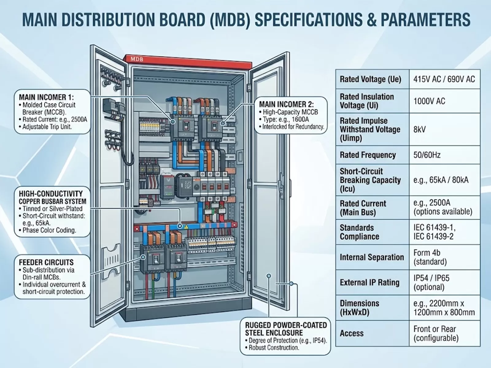
Yes, modern PFC units are highly modular. They can be installed as standalone cabinets or directly bus-connected alongside your main electrical panels.
Q4: What maintenance does an APFC system require?
Routine maintenance is minimal but crucial. You should check cooling fan operation, inspect for swollen capacitors, and verify tight busbar connections every six months.