
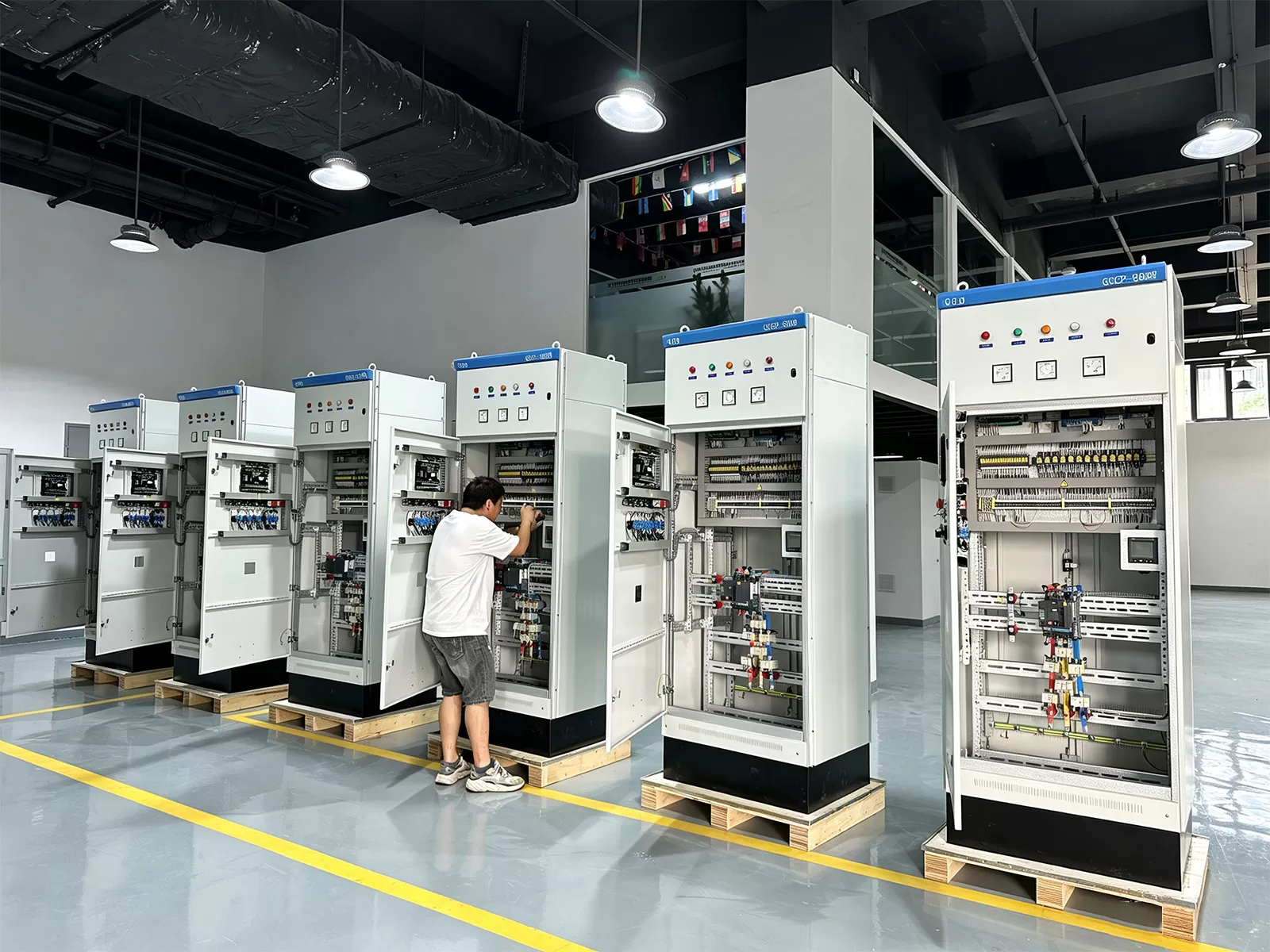
Industrial electrification networks are undergoing a fundamental architectural transition. Where power distribution systems once served merely as static conduit pathways for electrical energy, modern manufacturing and automated processing plants require dynamic, intelligent, and highly resilient infrastructures. Within this technical paradigm, the contemporary db panel board acts as the critical operational nucleus bridging medium-voltage sub-stations to downstream programmable logic controllers, variable frequency drives, servomotors, and critical process machinery.
Accommodating the aggressive operational tempos of automated manufacturing demands robust switchgear assemblies capable of withstanding dynamic thermal stresses, intermittent transient overvoltages, and relentless duty cycles. Designing or specifying power distribution apparatus requires an exhaustive understanding of international safety mandates, thermal dynamics, short-circuit withstand capabilities, and communication topologies.
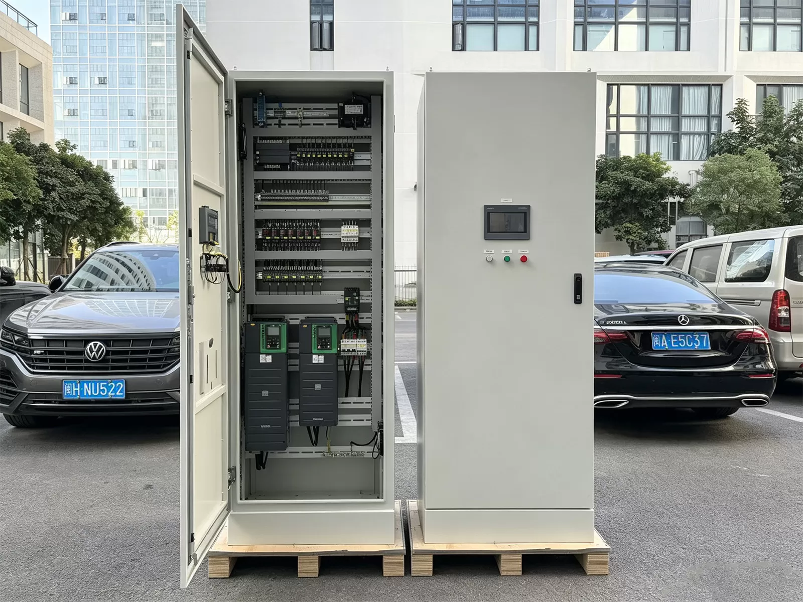
.webp?t=1789440707129 "db panel board")
Specifying a Robust DB Panel Board for Heavy Industrial Environments
Deploying electrical equipment into severe operating conditions necessitates a stringent approach to structural and mechanical engineering. In industrial automated plants, switchgear frequently contends with ambient temperature swings, airborne particulates, conductive dust, moisture ingress, and localized vibration induced by heavy rotating equipment.
Specifying an industrial enclosure demands close attention to international standardization frameworks, primarily IEC 61439-1/2 for low-voltage switchgear and controlgear assemblies, alongside UL 891 or UL 67 in North American jurisdictions. These benchmarks govern critical engineering parameters:
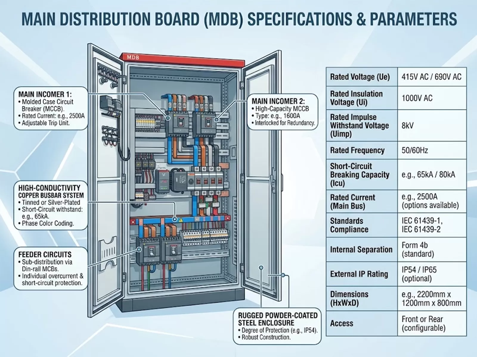
Internal Forms of Separation: Mitigating risk begins with structural segregation. While commercial installations commonly employ Form 1 or Form 2 configurations, mission-critical industrial manufacturing demands Form 3b, Form 4a, or Form 4b internal separation. Form 4b physically partitions the main busbars from functional units, isolates functional units from one another, and segregates outgoing termination points. This construction prevents accidental contact, stops propagated fault arcs, and allows maintenance personnel to service individual circuits while adjacent sections remain energized.
Busbar Metallurgy and Dynamic Electrodynamic Resistance: High-purity Electrolytic Tough Pitch (ETP) copper (grade Cu-ETP CW004A, exceeding 99.9% electrical conductivity) forms the benchmark for main horizontal and vertical distribution busbars. Sizing must calculate not only steady-state thermal current carrying capacity but also electrodynamic short-circuit limits. When a bolted three-phase fault occurs, peak electromagnetic forces exert severe mechanical loads across supports. Utilizing glass-fiber-reinforced polyester or cycloaliphatic epoxy resin insulators with high creepage distances ensures the busbar system maintains structural integrity under fault conditions up to 50 kA, 65 kA, or 100 kA for a 1-second duration ($I_{cw}$).
Enclosure Protection and Coatings: Enclosures deployed in heavy industrial settings typically demand ingress ratings of IP54, IP55, or IP65. Sheet metal fabrication requires minimum 1.5 mm to 2.0 mm electro-galvanized or cold-rolled mild steel treated with a thermoset polyester powder coat finish applied via automated electrostatic systems. In highly corrosive processing areas, such as chemical facilities, grade 316L stainless steel enclosures provide the primary defense against atmospheric chemical degradation.
Engineering partners such as XDEPE offer tailored modular switchgear architectures, configuring custom internal segregation systems and engineered busbar profiles that match precise spatial footprints and prospective fault levels within continuous-process industrial plants.
Overcoming Electrical and Thermal Bottlenecks in Switchgear Integration
Thermal accumulation represents the primary operational threat to switchgear lifecycle reliability. As automated operations increase power density by packing dense rows of miniature circuit breakers (MCBs), molded case circuit breakers (MCCBs), harmonic filters, contactors, and control relays into enclosed volumes, internal ambient temperatures rise rapidly.
Excessive internal heat accelerates the degradation of insulation materials, causes nuisance tripping of thermal-magnetic release mechanisms, and increases electrical contact resistance across terminal joints. Mitigating these conditions requires proactive engineering interventions during the design phase:
Thermal Modeling and Derating Protocols: Applying empirical derating coefficients ($k_t$) according to the ambient temperature within the switchroom is standard practice, but calculating internal compartmental temperature rise ($\Delta T$) is critical. For natural convection, ventilation louvers must be engineered with internal air velocity profiles that prevent dead zones. When forced ventilation or closed-loop air-to-air heat exchangers are necessary, the volume of air displacement must account for total internal component watt losses plus busbar resistive heating ($I^2R$).
Harmonic Current Dissipation: Non-linear industrial loads—such as variable frequency drives, induction furnaces, and high-frequency switching power supplies—introduce severe harmonic distortion (predominantly 3rd, 5th, 7th, and 11th orders) into the power distribution architecture. Triple harmonics in particular induce heavy currents in the neutral busbar, frequently exceeding the magnitude of the phase currents. Busbar design must expand neutral conductor cross-sections to 200% of the phase busbar area while employing de-rated, harmonic-rated switchgear components to avoid dangerous thermal buildup.
Cascading and Selective Discrimination: System resilience depends upon selective fault isolation. Engineers must implement comprehensive time-current coordination studies to achieve total discrimination between the main upstream air circuit breaker (ACB) or frame-size MCCB and downstream branch protection devices. An uncoordinated trip cascades backward, de-energizing an entire sub-distribution board, idling multiple automated lines, and inflicting significant financial downtime.
Collaborating with XDEPE technical specialists during the engineering phase enables precise thermal modeling and verified short-circuit calculation reviews, ensuring that specified protection equipment clears local fault currents without unnecessary plant-wide interruptions.
Digitalization and Smart Automation Interfacing
The traditional dumb distribution board is no longer viable within Industry 4.0 paradigms. Power distribution nodes must communicate bidirectionally with high-level Supervisory Control and Data Acquisition (SCADA), Energy Management Systems (EMS), and Distributed Control Systems (DCS).
Transitioning toward an intelligent platform involves embedding micro-instrumentation, continuous condition monitoring, and industrial network nodes directly within the assembly. Integrating smart I/O and communication protocols allows the db panel board to function as an active data hub on the factory floor.
Microprocessor-Based Circuit Breakers: Modern MCCBs and ACBs feature electronic trip units (ETUs) equipped with embedded Modbus RTU, Modbus TCP, Profinet, or EtherNet/IP communications. These devices deliver granular operational metrics, including phase currents, line-to-line voltages, active/reactive power, power factor, and individual harmonic distortion levels, straight to central plant control networks.
Contactless Infrared Temperature Monitoring: Traditional periodic infrared thermography provides merely a static snapshot of equipment health. Advanced digital boards now incorporate arrays of non-contact infrared thermal sensors or surface-mounted surface acoustic wave (SAW) sensors aimed directly at critical busbar splice joints and cable termination lugs. Real-time thermal telemetry alerts maintenance teams to rising contact resistance long before thermal runaway can trigger an arc flash incident.
Branch Circuit Power Monitoring (BCPM): High-density automated facilities deploy multi-channel current transformer arrays fitted over outgoing branch conductors. BCPM systems monitor multiple single-phase or three-phase branch circuits simultaneously, measuring sub-cycle load variations and providing predictive alerts when automated actuator motors show signs of bearing wear or mechanical binding.
Installation Standards, Cable Management, and Commissioning Verification
Mechanical installation and electrical commissioning dictate the operational longevity of heavy distribution assemblies. Even a meticulously engineered switchboard will fail prematurely if subjected to improper site integration, poor torque control, or flawed grounding methodologies.
Cable entry design represents a primary mechanical consideration. For large single-core power conductors carrying alternating currents, non-magnetic gland plates—typically manufactured from 3 mm to 5 mm non-ferrous aluminum or brass—are mandatory. Routing single-core cables through magnetic sheet steel induces localized circulating eddy currents, heating the entry plate to hazardous temperatures and compromising the integrity of conductor insulation.
During physical assembly, every electrical connection must be torqued precisely using calibrated torque wrenches according to the manufacturer's published engineering tables, followed by application of torque seal inspection lacquer. Over-tightening crushes soft copper conductors and strips internal threading, while under-tightening inevitably creates localized high-resistance joints that degrade under dynamic thermal cycling.
Pre-commissioning site testing must systematically follow international protocols:
Insulation Resistance Verification: Megohmmeter testing performed at 1000V DC between phases, and between phases and earth, ensuring minimum acceptable insulation resistance values exceeding 100 Megaohms post-installation.
Dielectric Withstand Testing (Hi-Pot): High-potential testing conducted at power frequencies to verify clearance and creepage parameters, confirming the absence of localized insulation breakdown across phase-to-phase and phase-to-ground barriers.
Contact Resistance Profiling: Micro-ohmmeter (ductor) testing across major current paths, main disconnect contacts, and busbar fishplate splices, ensuring contact resistance across interfaces remains within defined micro-ohm tolerances.
Lifecycle Reliability, Arc Flash Safety, and Predictive Maintenance
Occupational safety mandates require that the db panel board design actively mitigate arc flash hazards. Electrical arcs reach plasma temperatures exceeding 19,000 degrees Celsius in fractions of a second, vaporizing copper, creating catastrophic pressure waves, and posing lethal threats to plant operators.
Modern switchgear engineering counters this hazard by integrating internal arc fault containment methodologies conforming to IEC/TR 61641 standards. Internal arc-resistant enclosures incorporate pressure relief flaps, reinforced hinges, labyrinth-sealed door edges, and dedicated exhaust plenums to channel explosive gases up and away from operating personnel.
Active protection systems represent the pinnacle of modern switchgear safety. Fast-acting optical arc detection relays utilize fiber-optic point sensors or bare fiber loops distributed across busbar and cable compartments. When the sensor detects a high-intensity luminous burst coincident with a current surge, the trip signal is dispatched to the upstream breaker in under 1 to 2 milliseconds, clearing the fault well before the mechanical pressure peak can compromise the external housing.
Establishing predictive maintenance programs relies on continuous telemetry instead of scheduled shutdowns. Collecting vibration data from mechanical trip mechanisms, logging breaker cycle counts, monitoring partial discharge via transient earth voltage (TEV) sensors, and evaluating live busbar thermal trends creates an actionable asset performance profile. This approach enables plant engineers to overhaul functional units based on operational wear patterns rather than arbitrary calendar schedules, cutting unbudgeted operational expenditures.
Frequently Asked Questions
Q1: What is the primary difference between Form 2b and Form 4b
internal separation?
A1: Under IEC 61439-2, Form 2b isolates the
main busbars from all functional units, but outgoing cable terminals are not
separated from the busbars, nor are functional units separated from one another.
Form 4b delivers complete physical isolation: the main busbars are isolated from
functional units, all functional units are isolated from each other, and the
outgoing termination points for each functional unit are completely segregated
within dedicated, individual compartments. Form 4b provides the highest
operational safety for servicing live switchgear.
Q2: Why must neutral busbars be oversized when specifying equipment
for industrial automated machinery?
A2: Automated facilities rely
heavily on switched-mode power supplies, variable speed drives, robotics, and
LED drivers. These non-linear loads produce triplen harmonics (specifically the
3rd, 9th, and 15th harmonic orders). Unlike fundamental currents that cancel
each other out in a balanced three-phase system, triplen harmonics add
arithmetically in the neutral conductor. This additive effect can cause neutral
currents to exceed phase currents by 130% to 200%, requiring neutral conductors
and busbars to be sized to double the phase busbar capacity to prevent
catastrophic overheating.
Q3: How does electrodynamic withstand rating ($I_{pk}$) differ from
short-time withstand rating ($I_{cw}$)?
A3: The short-time withstand
current ($I_{cw}$) measures the thermal capacity of the busbar system and
structural supports to absorb the thermal energy ($I^2t$) generated by a
continuous fault current over a defined time, typically 1 or 3 seconds. The peak
withstand current ($I_{pk}$) measures the structural, mechanical strength of the
busbar supports and bracing to resist the immediate, massive electrodynamic
magnetic repulsion forces generated during the first peak half-cycle of a
short-circuit fault.
Q4: When should aluminum busbars be considered instead of copper for
industrial distribution?
A4: While copper remains the industry
standard due to its high conductivity, superior mechanical tensile strength, and
low thermal expansion rate, modern copper-clad aluminum or high-grade treated
aluminum alloy busbars are occasionally evaluated for weight-sensitive or
cost-critical applications. However, in aggressive industrial environments
containing chemical vapors or high vibration, copper remains the preferred
engineering choice because aluminum experiences higher galvanic oxidation at
bolted joints and exhibits cold flow (creep) under sustained mechanical
compression.
Q5: What critical considerations dictate the selection of breaker
cascading versus full selectivity?
A5: Cascading allows downstream
circuit breakers with lower breaking capacity than the prospective short-circuit
current to be installed, relying on an upstream breaker to assist in breaking
the fault. While this configuration reduces initial capital costs, it introduces
the risk of upstream tripping, de-energizing unaffected parallel circuits. Full
selectivity (discrimination) ensures that only the protective device immediately
upstream of the fault opens, keeping the remainder of the plant fully
operational. For automated processing facilities where downtime carries high
operational costs, full discrimination is the preferred design approach.
Technical Consultation and System Specification
Specifying high-performance power distribution apparatus demands engineering precision, rigorous adherence to compliance mandates, and deep operational expertise. For project-specific short-circuit analyses, thermal management evaluations, or customized modular switchgear assemblies engineered to your facility's operational parameters, engage with XDEPE technical engineering teams via email at yoyo@xdepe.com to review your single-line diagrams and application requirements.




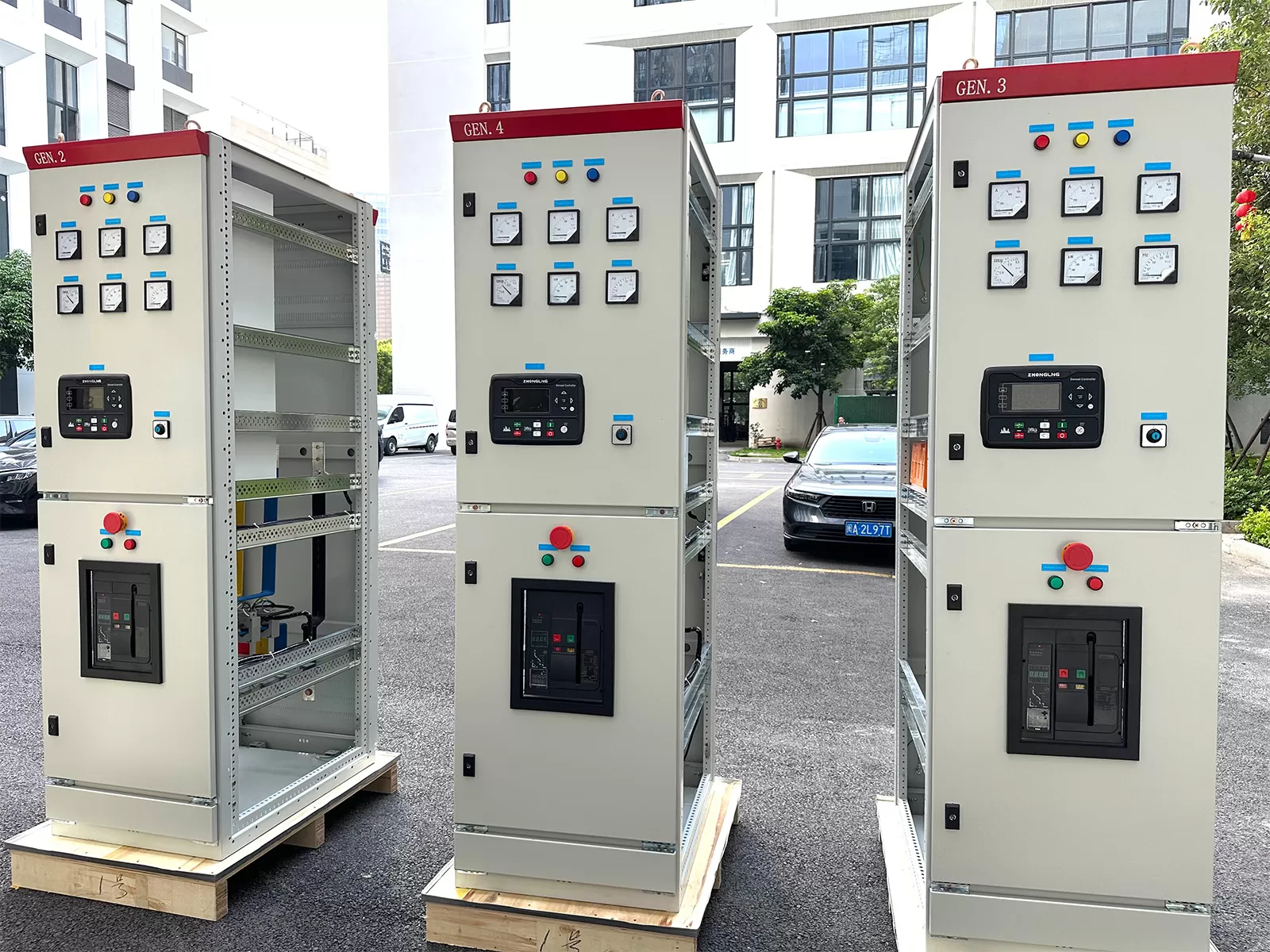
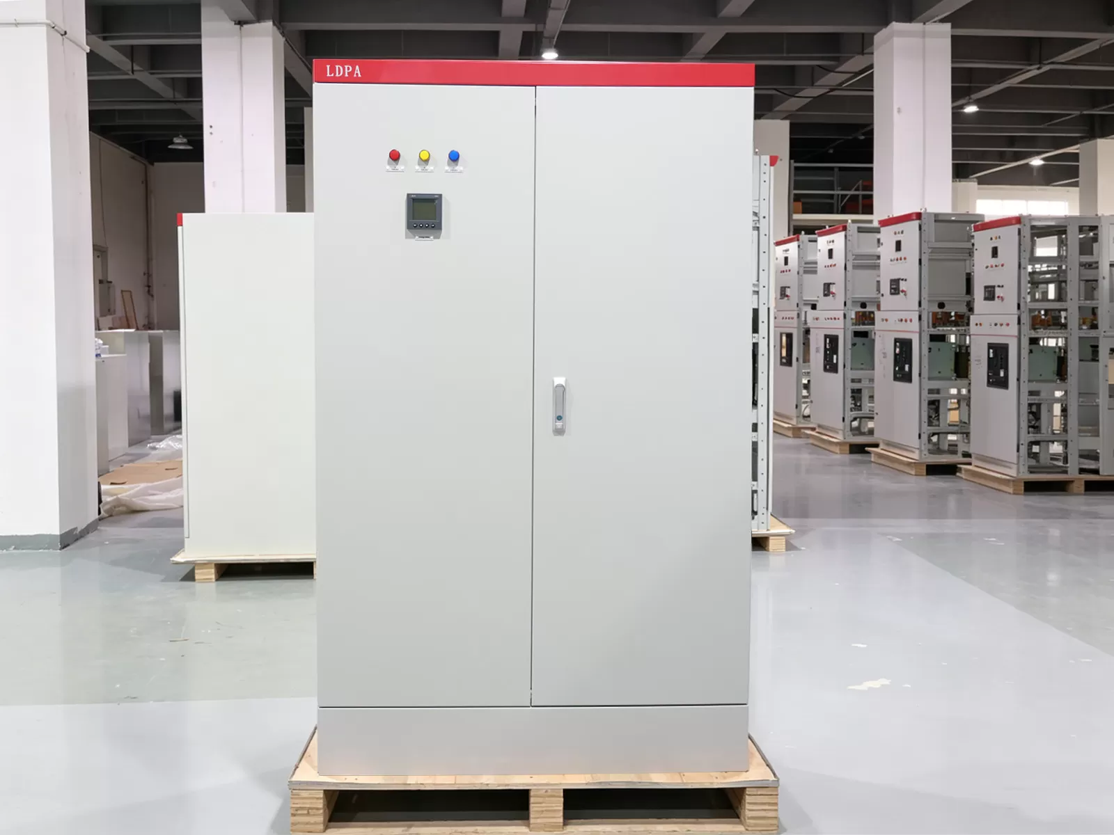

.webp?t=1787649054185 "22-Day Delivery: 50kW Sync Panels to Philippines")