
Serving as the central operational hub for production machinery, an industrial control panel regulates power distribution, signal translation, and programmatic logic execution across factory environments. Modern manufacturing demands unprecedented levels of uptime, precision, and deterministic networking, transforming these enclosures from passive junction points into sophisticated electromechanical ecosystems. Designing, manufacturing, and deploying such systems involves balancing strict regulatory compliance, thermal dissipation demands, electromagnetic compatibility, and long-term serviceability. For plant managers, automation engineers, and procurement directors, evaluating enclosure architecture through an exhaustive technical lens protects capital investments and reduces unexpected commissioning bottlenecks.
Regulatory Frameworks and Electrical Safety Compliance
Electrical enclosure architecture begins with stringent alignment to international safety codes. Discrepancies between regional requirements frequently cause installation delays or catastrophic equipment failures during field validation. In North America, the governing standard is UL 508A for industrial enclosures, operating in tandem with NFPA 79 for industrial machinery. European and international installations adhere primarily to IEC 60204-1 for machine electrical safety, along with the IEC 61439 series for low-voltage switchgear and controlgear assemblies.
A primary design parameter under both UL and IEC jurisdictions is the calculation of the Short-Circuit Current Rating (SCCR). Determining overall SCCR requires identifying the weakest component in the power circuit path based on maximum prospective fault currents. Engineers must examine every power distribution block, circuit breaker, fuse holder, motor starter, and variable frequency drive. Implementing coordinated component combinations, such as upstream current-limiting Class J or CC fuses, elevates the overall assembly SCCR to meet available utility fault levels without requiring massive over-sizing of downstream contactors.
Personnel protection mandates explicit mechanical and electrical fail-safes. Enclosure disconnect switches must incorporate mechanical door interlocks, ensuring the cabinet cannot be opened while high-voltage busbars remain energized, unless defeated by qualified maintenance personnel via a designated bypass tool. Internal dead-front covers, touch-safe terminal blocks rated to IP20 minimum, and protective finger guards across bus connections eliminate accidental contact with energized circuits during troubleshooting.
Internal Topography, Spacing, and Component Organization
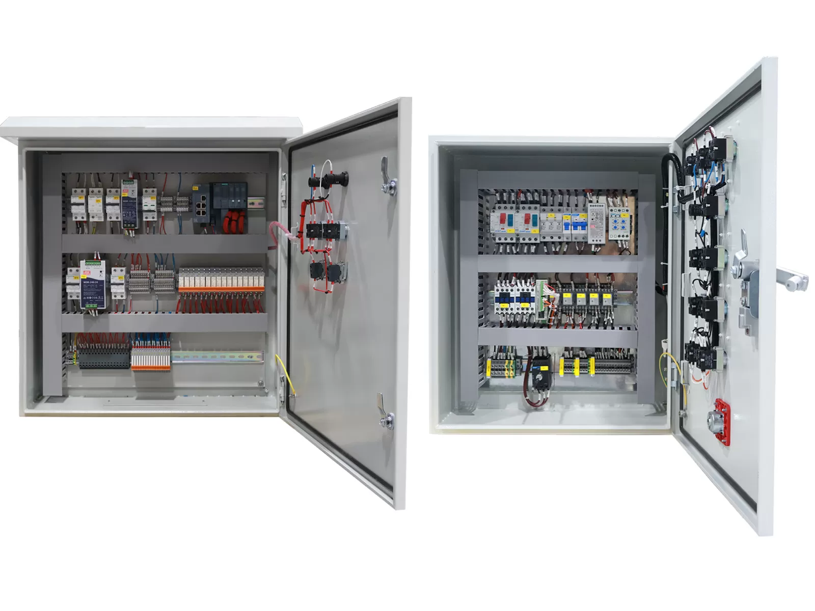
Logical component placement inside an enclosure dictates electrical reliability, electromagnetic isolation, and ease of routine servicing. DIN rails and wiring ducts partition the backplate into distinct functional zones. Power components operating at elevated voltages reside near the main incoming disconnect, typically in the upper quadrant, minimizing the transit length of heavy-gauge feeder conductors.
Voltage Segregation: High-voltage three-phase AC lines (480V/400V) must maintain spatial separation from low-voltage direct current (24V DC) logic signals and analog sensor wiring. Running these conductors in separate horizontal and vertical wire ducts eliminates inductive cross-talk and capacitive transient coupling.
Wire Duct Capacity: Wire duct sizing must respect maximum volume filling rules, ideally maintaining a 40% to 50% air gap for thermal dissipation and future circuit expansion. Overpacked raceways compress insulation, trap heat, and complicate wire tracing during maintenance.
Clearance Boundaries: Switching devices, particularly contactors and variable frequency drives, demand designated clearance zones above and below their chassis for convection currents and exhaust fans. Installing ducting too close to a heat sink restricts airflow and causes premature thermal tripping.
Terminal Density: DIN rail terminal blocks must provide clear grouping, utilizing color-coded blocks for ground (green/yellow), neutral (blue), 24V DC common (black/red), and analog loops. Sufficient spacing between adjacent terminal strips ensures technicians can route, land, and torque conductors without bending wires beyond their specified minimum bend radii.
Thermal Dynamics and Enclosure Climate Management
Every active semiconductor, power supply, transformer, and contactor coil releases thermal energy inside the sealed housing. Allowing internal ambient temperatures to rise beyond 40°C degrades electronic component lifespans exponentially, accelerating the drying of electrolytic capacitors in programmable logic controllers and variable speed drives. Calculating enclosure thermal balance requires assessing total internal wattage dissipation against external surface area heat transfer.
The heat transfer equation determines whether passive convection or closed-loop forced cooling is mandatory. When the ambient temperature outside the cabinet is consistently lower than the desired internal operating envelope, sealed filter fans using forced laminar flow can suffice. Environments laden with oil mist, conductive metal dust, or washdown fluids demand sealed NEMA 4, 4X, or IP65/IP66 ratings, rendering open-air ventilation unusable.
Engineers must deploy closed-loop air conditioners, air-to-air heat exchangers, or thermoelectric coolers in harsh environments. Air conditioners segregate the internal air volume from ambient contamination while drawing internal cabinet air through an evaporator coil to strip latent heat and humidity. Condensate management must be integrated into the cabinet base using automated vaporizers or drain conduits to prevent internal liquid accumulation. When configuring specialized motion systems or multi-axis machining cabinets, engineering teams consult with manufacturing specialists like XDEPE to calculate accurate heat-load balances and select enclosure cooling units matched to localized thermal profiles.
Electromagnetic Compatibility and Noise Mitigation
High-speed switching devices, notably the insulated-gate bipolar transistors (IGBTs) found in variable frequency drives and servo systems, introduce extreme rates of voltage change (dv/dt). These transients generate severe radiated and conducted electromagnetic interference (EMI). Without comprehensive shielding and bonding techniques, this noise couples onto sensitive industrial Ethernet communication links, analog 4-20mA process signals, and encoder feedback lines.
Effective noise mitigation requires establishing a unified, low-impedance ground plane across the entire enclosure. Zinc-plated or unpainted galvanized subpanels provide superior high-frequency bonding compared to painted steel panels where paint must be scraped away at every mounting stud. Star-grounding topologies ensure each functional subassembly references a common ground bus, eliminating ground loops caused by circulating shield currents.
Cable Shield Termination: Motor power cables carrying pulse-width modulated (PWM) outputs require full 360-degree circumferential shield grounding clamps directly at the drive output and at the enclosure entry bulkhead. Pigtail ground terminations act as high-frequency antennas and must not be used.
Line Reactors and Filters: Installing passive harmonic line reactors or active harmonic filters on the line side of power converters suppresses high-frequency harmonics injected back into the facility distribution grid. Output dV/dt filters suppress voltage reflection spikes that destroy motor winding insulation on long cable runs.
Ferrite Suppression: Ferrite chokes installed over DC bus conductors, communication lines, and digital sensor inputs absorb high-frequency transient oscillations without impacting baseband signal transmission.
Programmable Architectures, Networking, and Field Interfacing
Industrial automation environments prioritize distributed, determinative connectivity over bulky point-to-point discrete wiring. The central programmable logic controller (PLC) communicates with remote I/O modules, human-machine interfaces (HMIs), vision sensors, and field instrumentation over deterministic industrial Ethernet protocols such as PROFINET, EtherNet/IP, or EtherCAT.
Managed industrial Ethernet switches mounted internally provide Quality of Service (QoS) packet prioritization, virtual local area network (VLAN) segregation, and Rapid Spanning Tree Protocol (RSTP) redundancy. The internal communication backbone isolates field-level sensor networks from facility-wide supervisory control and data acquisition (SCADA) systems, enhancing both functional safety and operational cybersecurity.
External field wiring interfaces require ruggedized bulkhead pass-through systems. Using split cable glands with modular elastomeric inserts allows pre-terminated industrial patch cables to enter the enclosure without cutting connectors or violating the structural ingress protection rating. Integrating point-of-entry surge protective devices (SPDs) safeguards internal microprocessor boards against external lightning-induced surges and inductive kickback from disconnected inductive loads.
Procurement Specifications and Collaborative Control Panel Verification
Procuring custom electrical systems requires evaluating complex schematic designs, bill of materials (BOM) resilience, and supplier manufacturing capabilities. Specifying teams must balance standardized commercial-off-the-shelf (COTS) components with application-specific tailoring to safeguard against localized supply chain interruptions and operational obsolescence.
Comprehensive schematic packages, developed via professional electrical CAD suites such as EPLAN or AutoCAD Electrical, serve as the technical foundation for production. These schematics must include complete point-to-point wiring diagrams, terminal allocation charts, power distribution single-line drawings, and automated cross-referencing for contactor coils and contacts. Engaging collaborative design support from technical manufacturers like XDEPE during early engineering phases ensures schematics are reviewed for physical wire routings, correct thermal distribution, and regional regulatory compliance before fabrication begins.
Quality assurance protocols prior to shipment dictate project lead-time reliability. Comprehensive factory acceptance testing (FAT) incorporates cold continuity checks, insulation resistance (Megger) testing at 500V or 1000V DC, high-potential (Hi-Pot) dielectric testing, and complete dry-run energization to validate firmware, I/O mapping, and safety interlock functionality. Detailed FAT documentation eliminates field-commissioning anomalies that stall line-side integration.
Commissioning, Preventative Maintenance, and Lifecycle Reliability
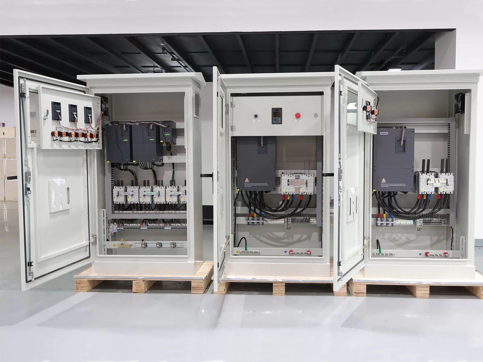
Once positioned on the manufacturing floor, the electrical assembly enters its commissioning phase. Physical anchoring must account for operational vibrations generated by neighboring stamping presses, CNC mills, or conveying lines. Shock-absorbing isolators and heavy-gauge seismic brackets prevent structural flexing that stresses internal rail mountings and electrical terminations.
Pre-commissioning torque audits represent a fundamental preventative measure. Screw-type terminal blocks and high-amperage busbar bolts loosen during transit due to micro-vibrations. Technicians must inspect and verify every fastener against specified torque ratings using calibrated torque screwdrivers and wrenches, applying torque-seal tamper paint across torqued points to provide visual verification during future inspections.
Operational maintenance strategies rely increasingly on condition-based monitoring rather than fixed calendar schedules. Thermographic inspection via infrared imaging windows enables technicians to scan internal power distribution blocks, contactors, and disconnect switches under full electrical load without removing protective dead-front panels or exposing themselves to arc flash hazards. Localized hot spots identify high-resistance terminations or impending contactor pitting long before an unscheduled thermal shutdown halts production.
Specifying clear terminal documentation, short-circuit current ratings, and field wiring provisions ensures the finished control panel delivers decades of operational stability with minimal lifecycle downtime. Partnering with seasoned manufacturing platforms like XDEPE grants machine builders direct access to tailored backplate layouts, precision harness manufacturing, and automated enclosure machining that optimize every square centimeter of internal volume.
Frequently Asked Questions
Q1: How is the overall Short-Circuit Current Rating (SCCR) determined for an industrial enclosure?
A1: Under UL 508A Supplement SB, the overall SCCR is determined by analyzing every component in the main power circuit, including disconnect switches, branch circuit protective devices, power blocks, motor contactors, and overloads. The assembly's SCCR defaults to the lowest-rated individual component in the power circuit, unless tested combinations or upstream current-limiting devices (such as designated fuses or current-limiting breakers) are engineered to protect downstream components up to a higher fault current rating. Control circuit components connected to the secondary side of a control transformer or regulated DC power supply do not affect the overall SCCR.
Q2: What calculation determines whether an enclosure requires an active cooling unit instead of basic ventilation?
A2: The calculation relies on the total internal heat dissipation (Q_internal, in Watts) and the enclosure's effective surface area (A, in square meters). The basic heat transfer through enclosure walls is calculated as Q_transfer = k × A × (T_internal - T_ambient), where k is the heat transmission coefficient of the enclosure material. If the ambient plant temperature exceeds the maximum allowable internal temperature (meaning T_ambient is greater than T_internal), heat flows into the cabinet from outside, rendering passive ventilation useless. Under these conditions, or when internal heat generation exceeds passive dissipation capacity while maintaining the target internal temperature (typically 35°C), active refrigeration cooling is mathematically mandatory.
Q3: What are the primary spacing rules to prevent electromagnetic interference between VFDs and sensitive sensors?
A3: Best practice dictates maintaining a minimum physical separation of 200mm to 300mm between unshielded 480V/400V variable frequency drive output cables and low-voltage analog (e.g., 4-20mA, 0-10V) or digital communication cables. When high-voltage power cables and signal cables must cross, they should cross exclusively at a 90-degree right angle to minimize mutual inductance. Additionally, variable frequency drives must be installed with continuous metallic bonding to a common subpanel, and power cables must be routed in grounded metallic conduit or enclosed wireways separate from sensitive data lines.
Q4: What is the fundamental difference between NEMA ratings and IP ratings for electrical cabinets?
A4: Ingress Protection (IP) ratings, defined under IEC 60529, classify protection levels against the ingress of solid foreign objects (first digit, 0-6) and liquids (second digit, 0-9K). National Electrical Manufacturers Association (NEMA) ratings, defined in NEMA Standard 250, evaluate identical ingress factors but also mandate testing for environmental durability that IP ratings omit. NEMA standards evaluate resistance to internal corrosion, external ice formation, gasket aging, oil and coolant seepage, and mechanical construction standards. While a NEMA rating can be loosely mapped to an equivalent IP rating (e.g., NEMA 4 to IP66), an IP rating cannot be converted into an equivalent NEMA rating because mechanical durability and corrosion resistance are not evaluated under IEC 60529.
Q5: When should an engineer select safety relays versus an integrated safety PLC?
A5: The selection depends on the total count and complexity of safety functions required by the machine's risk assessment (under ISO 13849-1 or IEC 62061). If an installation incorporates three or fewer discrete safety devices—such as two emergency stop pushbuttons and a single safety interlock gate—hardwired dual-channel safety relays represent the most cost-effective and straightforward solution. When an assembly incorporates multiple safety zones, light curtains, safety mats, robotic cell interlocks, and safe-motion drive interfaces, a safety PLC becomes necessary. Safety PLCs consolidate wiring, eliminate dozens of dedicated relays, enable configurable logic changes without rewiring, and deliver granular diagnostic data across industrial networks to upstream HMIs.
For technical inquiries, bespoke engineering specifications, or schematic verification on upcoming automation projects, contact the system integration engineering desk at yoyo@xdepe.com to coordinate detailed design reviews and production planning.





.webp?t=1787649054185 "22-Day Delivery: 50kW Sync Panels to Philippines")
.webp?t=1787648147488 "Xdepe 100% FAT Protocol Ensures Zero-Defect Electrical Cabinets")
.webp?t=1787647313485 "Top 10 Power Distribution Cabinet Manufacturers")
.webp?t=1787642349973 "Xdepe HV & LV Electrical Cabinets Achieve Full CE Certification")
.webp?t=1787641839853 "Top 10 Floor-Standing Electrical Cabinet Manufacturers")