
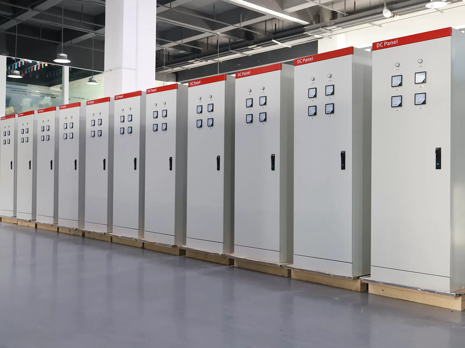
Heavy manufacturing environments push electrical systems to their absolute limits. Voltage sags, harmonic distortions, and unexpected breaker trips halt production lines and quickly turn profit margins into steep operational losses. At the center of every resilient industrial power system sits the 3 phase electrical distribution box.
Far from being just a passive steel cabinet, this unit functions as the operational heart of your facility. It routes high-current feeders, isolates line faults, and balances demanding industrial loads. When properly configured, it safeguards multi-million-dollar machinery from catastrophic failures.
At XDEPE, we design industrial power distribution hardware built to withstand rigorous operating conditions. If your manufacturing plant faces recurring electrical faults, higher-than-expected energy bills, or erratic machine trips, read through this optimization guide. Then, speak with our engineering staff to review your system topology.
.webp?t=1792635018924 "3 phase electrical distribution box")
1. Calculate Inrush Loads and Establish Real-World Thermal Margins
Heavy manufacturing equipment rarely operates with uniform, linear power profiles. Heavy-duty equipment—such as multi-axis CNC machines, hydraulic presses, and injection molding machinery—demands immense inrush currents during motor startup. These startup surges frequently reach six to eight times the continuous full-load amperage (FLA).
If you size your 3 phase electrical distribution box solely based on steady-state continuous loads, internal breakers will experience nuisance tripping. Furthermore, continuous operation close to maximum capacity causes internal heat buildup, which leads to thermal derating of sensitive switches and protective relays.
- Calculate Peak vs. Continuous Amps: Map the total combined running load of your machinery, then add the maximum locked-rotor amperage (LRA) of the largest single motor that could start simultaneously.
- Implement the 20-25% Expansion Rule: Always leave at least 20% to 25% spare electrical and physical capacity inside the enclosure. This buffer absorbs momentary spikes without thermal stress and allows for future plant expansion without replacing the primary enclosure.
- Compensate for Ambient Plant Temperature: Standard breaker ratings assume an ambient external temperature of 40°C (104°F). If your plant floor exceeds this baseline during peak summer operations, derate your breakers according to manufacturer guidelines to avoid false trips.
2. Balance Phase Loads to Protect Motors and Neutral Conductors
Imbalanced phase currents are a quiet, costly issue in manufacturing plants. When single-phase loads (such as auxiliary heaters, control panels, plant lighting, and localized PLCs) draw power unevenly across your three-phase supply, voltage unbalance occurs.
A mere 2% to 3% voltage unbalance between phases can cause an 18% to 25% temperature rise in an AC induction motor. This extra heat destroys motor winding insulation, introduces mechanical vibration, and places dangerous current onto the neutral busbar.
To eliminate this risk, adopt disciplined load scheduling inside your 3 phase electrical distribution box:
- Distribute Single-Phase Loads Symmetrically: Map your branch single-phase circuits evenly across Phase A (L1), Phase B (L2), and Phase C (L3). Use a dual-element clamp meter during a standard shift to confirm current equilibrium within 5% across all three phases.
- Mitigate Harmonics from Variable Frequency Drives (VFDs): Non-linear loads like VFDs, servo controllers, and robotic welding rigs inject harmonic currents back into the feeder line. These cause transformer losses and busbar overheating.
- Install Active or Passive Harmonic Filters: Locate tuning reactors or active harmonic filters directly upstream or within your distribution enclosure to maintain Total Harmonic Distortion (THD) within IEEE 519 compliance standards.
3. Specify Superior Busbars and Coordinated Circuit Protection
A well-optimized 3 phase electrical distribution box relies heavily on the quality of its internal conductors and the speed of its protective switchgear. Thin, low-grade copper or unplated aluminum busbars create excessive contact resistance, creating dangerous localized hot spots under heavy loads.
High-Conductivity Tinned Copper Busbars
Always specify solid, high-purity electro-tin-plated copper busbars (99.9% Cu ETP) over aluminum. Tin plating stops copper oxidation, resists corrosive airborne contaminants, and lowers joint resistance. Ensure the busbar cross-section matches both your continuous amperage needs and the prospective short-circuit fault current (kA rating) of your local substation.
Tiered, Cascading Circuit Protection
Coordinate breaker trips across all levels of your distribution system:
- Main Incoming Unit: Install an adjustable Molded Case Circuit Breaker (MCCB) or Air Circuit Breaker (ACB) equipped with an electronic trip unit (ETU) to manage Long-time (L), Short-time (S), Instantaneous (I), and Ground-fault (G) protection settings.
- Branch Distribution: Deploy individual thermal-magnetic or electronic MCCBs for heavy equipment feeds, and Miniature Circuit Breakers (MCBs) with Type C or D trip curves for motor circuits and inductive loads.
- Residual Current Devices (RCDs): Integrate earth leakage protection to shield personnel and expensive control circuitry against low-level ground faults that might not trigger standard overcurrent trips.
- Surge Protective Devices (SPDs): Industrial inductive load switching creates massive voltage spikes. Fit high-energy Type 1+2 SPDs right at the incoming busbar connections to protect sensitive machine electronics against lightning strikes and power switching transients.
Engineers at XDEPE configure custom breaker coordination setups to isolate electrical faults at the local branch, keeping the main incoming circuit online and protecting unaffected assembly lines.
4. Improve Thermal Management and Rugged Enclosure Durability
Manufacturing facilities are harsh environments. Metal chips, oil aerosols, airborne dust, and high ambient temperatures threaten electrical reliability. Heat buildup inside a tightly sealed enclosure remains a primary cause of unexpected equipment failure.
Choosing the Correct Ingress Protection (IP) Rating
Selecting the wrong enclosure rating guarantees shortened component lifespans. Standard office or commercial enclosures cannot handle factory conditions:
- IP54 / IP55: Suitable for standard workshop environments with limited splashing water and non-conductive dust.
- IP65 / NEMA 4: Essential for processing zones that face washdown cycles, high concentrations of conductive dust, or constant oil-mist exposure from coolants.
Active and Passive Thermal Management
Do not depend on natural cabinet convection if your internal continuous heat dissipation exceeds 500 Watts. Trapped heat dries out capacitor electrolytes and raises internal resistance:
- Component Spacing: Maintain clear air channels between high-amperage breakers. Avoid grouping heat-generating components, such as control transformers, directly beneath sensitive monitoring relays.
- Forced-Air Cooling vs. Closed-Loop Cooling: While louvered intake fans with replaceable particulate filters work in dry, clean zones, humid or oily factories require closed-loop cooling. Install industrial side-mount heat exchangers or cabinet air conditioners to cool internal air without drawing in plant-floor contaminants.
- Vibration Isolation: Heavy machinery transfers mechanical vibrations through concrete floors, which can loosen electrical connections. Mount your 3 phase electrical distribution box using heavy-duty vibration-damping brackets and add spring washers or serrated flange nuts to internal busbar joints.
5. Deploy Predictive Monitoring and Arc-Flash Defenses
Modern industrial management requires moving past reactive firefighting. You should not wait for smoke, a loud pop, or a tripped main breaker to recognize a failing distribution line. Integrating smart monitoring tools into your three-phase box shifts your team to an efficient, predictive maintenance model.
Modernized units use digital sensors that continuously track operating conditions:
- IoT Digital Power Meters: Equip each incoming busbar with multifunction smart meters that output RS-485 Modbus or Ethernet data. Track real-time phase balance, power factor, active/reactive energy, and total harmonic distortion (THD).
- Infrared (IR) Inspection Windows: Install transparent infrared sight glasses on the cabinet door. This allows maintenance technicians to run thermographic scans on primary cable terminations and breaker lugs without opening the enclosure or exposing themselves to live busbars.
- Continuous Contact Temperature Sensors: Mount non-contact infrared or wireless surface sensors directly onto critical cable junctions. Set warning thresholds to alert engineers over the plant SCADA system when a loose joint begins to heat up.
- Arc-Flash Optical Detection: Arc flashes can destroy equipment and cause severe injuries in milliseconds. Modern distribution enclosures use point optical sensors combined with instantaneous overcurrent sensors to trip upstream circuit breakers in under 10 milliseconds, containing potential arc flashes before they expand.
6. Standardize Maintenance Schedules and Ensure Regulatory Compliance
Even the most advanced distribution setup will fail if neglected. Regular preventive maintenance preserves the integrity of internal connections, ensures personal safety, and guarantees full compliance with regulatory frameworks like IEC 61439-1/2, UL 508A, or NFPA 70 (NEC).
- Torque Checks: Thermal cycling continuously expands and contracts metal connections, which loosens bolted joints over time. Use a calibrated torque wrench every six to twelve months to check all busbar splices and terminal lugs against the manufacturer’s specified Newton-meter (Nm) values.
- Insulation Resistance (Megohmmeter) Testing: Disconnect sensitive electronics and run an annual 1,000V DC megohmmeter test between phases and from phase-to-ground. A sharp drop in insulation resistance exposes failing cable jackets or internal surface contamination.
- Ground Continuity and Bonding: Verify low-impedance ground bonding between the enclosure frame, door, sub-panels, and incoming earth conductor. Ground resistance should consistently remain below 1.0 Ohm.
- Clean Internal Components: Use an industrial vacuum with an
anti-static nozzle to clear loose debris from breaker vents and busbar supports.
Never clean an active panel using high-pressure compressed air, as this drives
conductive dust into delicate switch mechanisms.
Maximize Your Industrial Uptime with Optimized Power Distribution
Optimizing your facility's 3 phase electrical distribution box delivers a clear return on investment. Sizing breakers to handle peak motor inrush, balancing current across phases, fitting tinned copper busbars, and installing closed-loop climate controls eliminates unexpected downtime and preserves expensive machinery.
Every industrial production environment brings its own specific power demands. Standard, off-the-shelf panelboards rarely provide the durability, monitoring capabilities, and fault tolerance demanded by heavy manufacturing machinery.
At XDEPE, we engineer and build custom, high-reliability industrial power distribution systems engineered around your exact manufacturing footprint. Whether you are expanding a machining line, revamping a manufacturing plant, or replacing aging hardware, our team can help.
Ready to protect your production lines from electrical failure? Contact the engineering team at XDEPE today to request a technical review and a fast, tailored quote.
Frequently Asked Questions (FAQ)
Q1: How do I know if my 3 phase electrical distribution box is overloaded?
A1: Common symptoms include warm enclosure panels, a persistent electrical hum, unexplained breaker trips during peak operations, and a low operating power factor. You can verify real loading levels by taking a true-RMS clamp meter reading or reviewing smart meter logs across all three phases during peak shift operations.
Q2: Why is my neutral wire overheating if my three-phase loads are balanced?
A2: Overheating neutrals in balanced systems are almost always caused by triplen harmonics (specifically the 3rd, 9th, and 15th harmonic orders) generated by non-linear electronics like VFDs, computer power supplies, and switched-mode drivers. These harmonic currents do not cancel out at the neutral node; instead, they add together on the neutral conductor. You can resolve this issue by upsizing your neutral busbar to 200% capacity and installing active harmonic filters.
Q3: What is the main difference between an MCB and an MCCB in heavy industrial applications?
A3: Miniature Circuit Breakers (MCBs) handle smaller branch currents (typically up to 100A or 125A) with fixed trip characteristics, making them suitable for low-power circuits and utility sub-distribution. Molded Case Circuit Breakers (MCCBs) handle currents up to 2,500A, offer adjustable trip settings, and provide significantly higher short-circuit interrupting ratings (often up to 100kA), which is necessary for high-fault-capacity heavy machinery lines.
Q4: How does unbalanced voltage affect my heavy three-phase motors?
A4: Voltage unbalance causes current unbalance that is 6 to 10 times higher than the original voltage deviation. This imbalance produces opposing magnetic fields inside the motor stator, creating extra heat, rotor chatter, increased operational noise, and accelerated winding degradation. Most motor warranties are voided if the drive is operated with more than 1% to 2% voltage unbalance.
Q5: Is air conditioning always required for an industrial 3 phase electrical distribution box?
A5: Air conditioning is not mandatory for every setup, but it becomes essential when the ambient plant temperature regularly exceeds 40°C (104°F), when the enclosure is sealed to IP65 levels without venting, or when it houses heat-generating equipment like VFDs, soft starters, and power supplies. Maintaining internal panel temperatures near 30°C to 35°C significantly extends breaker and electronics lifespans.




 Cabinet (1).webp "Automatic Transfer Switch (ATS) Failure: 5 Common Causes and How to Fix Them")
.webp "How to Select the Right 3 Phase Panel Board for Heavy Manufacturing Equipment")
 Switchgear (1).webp "What is a Withdrawable (Drawer-Type) Switchgear? A Complete Beginner's Guide")
.webp "Main Distribution Board vs. Sub Main Distribution Board: What's the Difference & How to Choose?")
