
Automated manufacturing environments rely on continuous, deterministic power delivery to maintain process integrity, sub-millisecond control loop accuracy, and plant safety. Within modern industrial facilities, the industrial db board functions as the critical node governing the transition between bulk high-voltage substation feeds and high-density, low-voltage control systems. Far from serving as a mere enclosure for circuit breakers, this power distribution layer must actively decouple upstream grid fluctuations from sensitive programmable logic controllers (PLCs), robotic kinematic cells, and distributed servo drives. Designing and specifying this infrastructure requires an exhaustive analysis of electrodynamic stress, thermal equilibrium, fault discrimination, and harmonic mitigation under demanding operational duty cycles.
The progression toward Industry 4.0 and lights-out fabrication lines intensifies the demands placed on electrical panels. Automated machinery introduces non-linear load profiles, rapid cyclic load variations, and continuous switching transients that standard commercial infrastructure cannot withstand. Consequently, systems engineering teams must adopt an integrated approach to power distribution. Evaluating busbar short-circuit capacity, selecting appropriate internal separation forms, and calculating heat dissipation under peak utilization ensures that downstream automated cells operate without unscheduled power interruptions or catastrophic failure events.

Foundational Architecture: Transforming Grid Feeds into Machine-Ready Power
Power distribution within industrial automation operates in a multi-tiered hierarchy. Primary electrical energy enters the facility via medium-voltage switchgear, is stepped down by dry-type or oil-immersed distribution transformers, and terminates at the Main Distribution Board (MDB). From the MDB, high-amperage sub-feeders route power across production halls directly to strategically located distribution units.
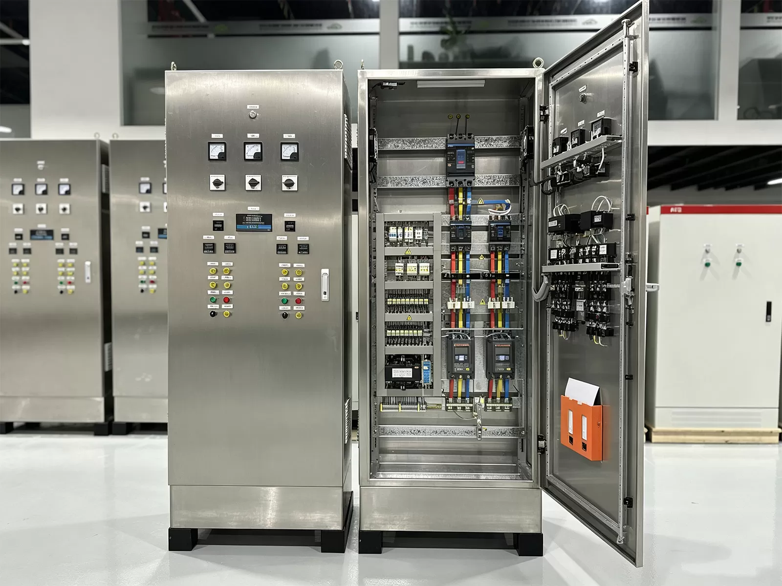
At this intermediate junction, incoming three-phase AC supplies (typically 400V to 480V) are segmented into manageable branch circuits. These branches feed motor control centers (MCCs), industrial automation control cabinets (IACCs), and dedicated pneumatic and hydraulic power packs. The internal layout of these assemblies determines how effectively electrical energy is compartmentalized to prevent cross-subsystem contamination during localized fault events.
International standard IEC 61439-2 classifies these internal topologies through clearly defined "Forms of Separation." Selecting the appropriate form defines operational accessibility and safety margins:
Form 1: Offers basic external enclosure protection with no internal physical barriers separating busbars, functional switching units, or output terminals. This configuration is generally unsuitable for harsh manufacturing spaces due to the risk of cascading arc events.
Form 2b: Separates the main busbars from functional units, with output terminals also isolated from the busbars. This topology reduces accidental contact hazards during routine maintenance on downstream automated machinery.
Form 3b: Isolates the main busbars from functional switching units, while functional units remain physically separated from one another. Terminals for external conductors are housed in distinct, segregated compartments, preventing localized terminal burnouts from damaging adjacent drive circuits.
Form 4b: The standard for continuous-process production environments. Main busbars, individual functional units, and all external cable termination points are completely separated from each other by metallic or insulating barriers. A failure inside an individual branch breaker does not compromise adjacent functional units, allowing hot-swapping or targeted servicing while the rest of the automation line remains active.
Technical Sizing and Electrical Performance Parameters
Selecting components for heavy manufacturing environments requires rigorous calculation of electrical, magnetic, and thermal stresses. Oversizing components incurs unnecessary capital expenditure, while undersizing drastically raises the probability of nuisance trips, copper fatigue, and insulation breakdown.
Short-Circuit Withstand Capacity
Every sub-distribution panel must withstand both the mechanical and thermal stresses generated during prospective short-circuit conditions until upstream protective devices clear the fault. Two critical parameters govern this requirement:
Rated Short-Time Withstand Current ($I_{cw}$): The root-mean-square (RMS) value of the fault current that the assembly can carry without sustaining physical or thermal damage for a specified duration (typically 1.0 or 3.0 seconds). Busbar bracing systems and insulating standoffs must be calculated against the peak dynamic electrodynamic forces ($I_{pk}$) generated during the initial quarter-cycle of a short circuit, where mechanical forces between parallel conductors increase with the square of the instantaneous peak current.
Rated Conditional Short-Circuit Current ($I_{cc}$): Applicable when coordinated upstream current-limiting protective devices, such as high-rupture-capacity (HRC) fuses or molded case circuit breakers (MCCBs), limit the peak let-through energy ($I^2t$) delivered into the internal bus structure.
Thermal Derating and Heat Dissipation Dynamics
Thermal accumulation within a sealed, ingress-protected enclosure represents a major failure vector for solid-state relays, programmable controllers, and circuit breaker trip mechanisms. Internal temperature rise ($\Delta T$) is governed by the total Joulean losses generated across internal components according to the formula:
$$P_{total} = \sum (I^2 \cdot R) + P_{parasitic}$$
In this relationship, $I$ represents the operational continuous current, $R$ denotes internal path resistance across busbars, connections, and contacts, and $P_{parasitic}$ accounts for continuous losses generated by power supplies, contactor coils, and metering units. Standard low-voltage components are calibrated for ambient room conditions of 25°C to 40°C. When enclosed inside an IP55 or IP65 assembly installed on an unconditioned factory floor, internal temperatures can easily surpass 60°C.
Operating under elevated temperatures shifts the thermal-magnetic trip curves of standard thermal trip elements downward, inducing nuisance tripping at currents below operational nameplate ratings. Electronic trip units (ETUs) with microprocessors must be deployed in high-temperature zones, paired with forced convective ventilation or closed-loop air-to-air or air-to-water heat exchangers that maintain interior cabinet temperatures below 40°C without compromising ingress ratings.
Harmonic Mitigation and Non-Linear Loads
The ubiquity of three-phase Variable Frequency Drives (VFDs), servo controllers, high-frequency induction heaters, and switch-mode power supplies creates a heavily distorted current waveform rich in odd harmonics (particularly the 3rd, 5th, 7th, 11th, and 13th orders). These non-linear loads introduce operational complexities that do not occur in conventional resistive or linear motor circuits:
Neutral Conductor Overheating: In balanced three-phase systems with pure sinusoidal currents, neutral current theoretically approaches zero. However, triplen harmonics (specifically the 3rd, 9th, and 15th orders) do not cancel out at the neutral node; they sum constructively. In automation plants with high numbers of single-phase DC switch-mode power supplies, neutral currents can reach 140% to 170% of the phase currents. Assemblies must consequently feature fully rated (100%) or double-rated (200%) neutral busbars.
Skin and Proximity Effects: High-frequency harmonic currents alter the effective cross-sectional area of solid copper conductors, pushing current density toward the conductor perimeter. This increases equivalent AC resistance, amplifying localized thermal generation across busbars and feeder terminations.
Engineering Specifications for Industrial db board Architectures
Achieving deterministic reliability across industrial installations requires translating theoretical sizing calculations into precise hardware construction standards. Deploying an industrial db board in harsh production environments means specifying structural, mechanical, and metallurgical characteristics capable of surviving continuous chemical and physical stress.
Busbar metallurgy dictates long-term electrical reliability. Conductors must be fabricated from high-conductivity electrolytic tough pitch (ETP) copper, designated as C11000 or CW004A, retaining an electrical conductivity of at least 100% IACS (International Annealed Copper Standard). Bare copper oxidizes rapidly when exposed to airborne sulfides, elevated humidity, or industrial cutting fluids. As a result, all primary distribution busbars, links, and connection flags should be electro-tin plated (5 to 10 microns) or silver-plated to preserve low contact resistance and prevent galvanic corrosion over multi-decade operating horizons.
Enclosure chassis construction demands heavy-gauge materials to support dynamic mechanical stresses. Cold-rolled sheet steel with a minimum thickness of 1.5 mm to 2.0 mm, or grade 304/316 stainless steel for food-grade, pharmaceutical, or corrosive marine-adjacent plants, provides the necessary physical rigidity. The enclosure finishing process must include a multi-stage iron-phosphate or zinc-phosphate pre-treatment followed by electrostatically applied polyester powder coating (typically RAL 7035 light grey), achieving a minimum thickness of 60 to 80 microns to withstand industrial washdowns and mechanical abrasion.
Ingress Protection (IP) ratings must be carefully aligned with localized plant zones according to IEC 60529:
IP42 / IP43: Appropriate only for dedicated, pressurized electrical substations or clean control rooms where environmental airborne contaminants and moisture are mechanically managed.
IP54 / IP55: The baseline standard for broad shop-floor installations. Provides protection against ingress of airborne dust in quantities sufficient to impair operation, as well as protection against water splashing from any direction.
IP65 / IP66: Mandatory for fabrication zones subjected to continuous high-pressure washdowns, high-velocity oil mists, or dense particulate matter, such as automotive machining centers, ceramic processing lines, and metallurgical casting floors.
Operational Challenges and Mitigations in Automated Environments
High-speed automation architectures create complex operational scenarios where standard electrical practices fall short. Addressing these issues early prevents catastrophic production interruptions.
A primary challenge involves capacitive earth leakage currents originating from long, shielded motor cables between VFDs and remote motors. The fast switching edges ($dv/dt$) generated by modern Silicon Carbide (SiC) or Insulated Gate Bipolar Transistor (IGBT) inverters inject high-frequency leakage currents into the protective earth (PE) system via cable capacitance. Traditional Type A or Type AC Residual Current Devices (RCDs) misinterpret these leakage profiles as structural ground faults, leading to recurrent tripping. The solution lies in deploying Type B or Type B+ residual current monitoring units, which reliably identify smooth DC residual currents, high-frequency AC leakage, and composite fault currents without spurious disconnection.
Another systemic vulnerability involves cascading trip sequences caused by improper breaker selectivity. In automated assembly lines, a short circuit in a minor auxiliary component—such as a 24V DC auxiliary power supply or a small motorized diverter—must never trip the upstream sub-distribution breaker, which would shut down the entire multi-station cell. Achieving absolute selectivity requires coordinating three overlapping protection domains:
Current Selectivity: Setting pickup thresholds such that downstream Miniature Circuit Breakers (MCBs) clear lower fault currents before the upstream MCCB's magnetic trip threshold is breached.
Time Selectivity: Utilizing short-time delay settings ($t_{sd}$) on upstream electronic trip units to introduce deliberate clearing delays (typically 50 to 300 milliseconds), giving downstream current-limiting devices the required window to extinguish localized arcs.
Energy Selectivity ($I^2t$ Discrimination): Comparing the total let-through clearing energy ($I^2t_{clear}$) of downstream branch devices against the upstream breaker's pre-arc melting energy ($I^2t_{melt}$) using manufacturer selectivity tables across all prospective short-circuit levels.
In highly complex automation layouts, the integration of a db board requires comprehensive system modeling. Specialized engineering partners, such as XDEPE, provide the technical support needed to model selective coordination curves, resolve complex thermal envelopes, and balance structural busbar topologies to eliminate protection overlap before hardware fabrication begins.
Physical Deployment, Cabling Infrastructure, and On-Site Commissioning
Even the most robustly calculated electrical design can fail if physical installation and mechanical termination standards are neglected. Cable management and electromagnetic compatibility (EMC) require disciplined engineering from the moment field wiring enters the enclosure.
Field cables carrying dirty, transient-heavy power to high-frequency actuators must enter the cabinet through dedicated gland plates physically separated from low-voltage DC communication and sensor cables. Conductive, 360-degree EMC brass cable glands should be installed to bond cable braided shields directly to the chassis ground plate at the entry threshold, shunting induced radio-frequency interference (RFI) straight to earth before it reaches internal bus infrastructure.
Internal copper bus joints and flexible copper braids must be fastened using high-tensile Grade 8.8 galvanized steel bolts paired with Belleville conical spring washers. These specialized washers maintain continuous mechanical tension over years of thermal expansion and contraction cycles. Every bolted connection must be tightened to specified torque values using calibrated torque tools and marked with permanent torque inspection paint to provide immediate visual confirmation of mechanical integrity during subsequent preventative plant audits.
Before bringing line voltage to the system, commissioning technicians must conduct a rigorous series of baseline tests:
Insulation Resistance Verification: Conducted using a calibrated megohmmeter applying 500V or 1000V DC between phases, and between phases and protective earth. Minimum allowable values must exceed 100 Megaohms, confirming that no insulation damage occurred during cable pulling or enclosure assembly.
Phase Sequence and Voltage Symmetry: Verifying clockwise phase rotation (L1-L2-L3) with a digital phase rotation indicator to ensure three-phase induction motors do not rotate in reverse upon startup, which could cause catastrophic mechanical damage to connected gearboxes and drive tooling.
Ground Continuity and Loop Impedance: Verifying that the resistance from the main earthing terminal to any metallic sub-panel, hinged door, or gland plate remains under 0.1 ohms, establishing a low-impedance path to ground that clears dangerous touch voltages safely.
Engineering workflows that coordinate with technical teams like XDEPE streamline custom gland plate configurations, optimize terminal density, and verify physical clearance constraints, accelerating commissioning across complex multi-axis automation lines.
Preventive Maintenance Protocols and Condition Monitoring
Maintaining peak operational availability across high-throughput production lines requires transitioning away from reactive maintenance toward predictive condition monitoring. Electrical distribution units should be inspected continuously or at fixed intervals using non-invasive analytical methods.
Infrared (IR) thermography is an essential diagnostic protocol. Periodic thermal imaging performed under at least 40% to 70% of continuous operational load identifies abnormal hot spots across internal components. A temperature differential ($\Delta T$) of 1°C to 10°C above adjacent phases indicates localized resistance buildup, usually due to a loose mechanical connection or contact surface oxidation. A $\Delta T$ exceeding 30°C signifies critical failure potential, demanding immediate circuit isolation and re-torque or component replacement.
To eliminate the arc-flash hazards associated with opening energized panels during manual thermal scanning, modern automation standards increasingly mandate the installation of permanently mounted infrared inspection windows (zinc selenide or polymer optic viewports) or real-time continuous thermal monitoring systems. These continuous systems utilize miniature fiber-optic or wireless surface acoustic wave (SAW) sensors affixed directly to critical busbar joints, continuously streaming temperature data to plant supervisory control and data acquisition (SCADA) platforms.
Secondary injection testing must be conducted on high-current incoming circuit breakers every 24 to 36 months. Using portable digital test kits, field service engineers inject simulated overcurrent, short-delay, and ground-fault signals directly into the solid-state trip unit logic board. This verifies that electronic trip mechanisms, flux-transfer shunts, and mechanical trip linkages unlatch within their calibrated millisecond tolerances, preserving primary asset protection.
Frequently Asked Questions
Q1: What structural differences distinguish an industrial
sub-distribution panel from a standard commercial unit?
A1:
Industrial distribution panels are engineered for severe operating environments,
characterized by high continuous load factors, wide ambient temperature swings,
heavy vibration from adjacent machinery, and elevated airborne contamination.
They feature thicker enclosure steel (1.5mm to 2.0mm+), higher short-circuit
withstand ratings ($I_{cw}$ up to 50kA or 65kA for 1 second), elevated internal
separation topologies (IEC 61439 Form 3b or 4b), tin- or silver-plated copper
busbars, and enhanced ingress protection ratings (IP54 to IP66), contrasting
with standard commercial panels designed primarily for clean, human-conditioned,
low-fault-current environments.
Q2: How is absolute breaker discrimination maintained across
automated factory floors?
A2: Absolute discrimination (or total
selectivity) is achieved when only the protective device immediately upstream of
an electrical fault trips, while all other upstream devices remain closed. This
requires coordinating the time-current curves (TCC) across all operating bands:
current threshold grading, intentional time delays using short-time delay
($t_{sd}$) settings on upstream electronic trip units, and matching the total
let-through energy ($I^2t$) of the downstream branch breaker to keep it below
the pre-arc melting threshold of the main breaker.
Q3: Why must the neutral busbar be oversized in plants utilizing
extensive automation drives?
A3: Industrial automation equipment
incorporates switch-mode power supplies, servo drives, and non-linear power
electronics that draw distorted current containing high concentrations of
3rd-order (and other odd triplen) harmonics. Unlike fundamental sinusoidal
currents that cancel out in three-phase systems, triplen harmonics add together
directly on the neutral conductor. This additive effect can cause neutral
currents to reach 140% to 200% of nominal phase currents, requiring neutral
busbars and terminal links to be sized at 100% to 200% of the phase busbar
capacity to prevent catastrophic overheating.
Q4: Which Ingress Protection (IP) rating is recommended for units
located near automated wet-machining or washdown areas?
A4: Panels
installed adjacent to machining centers utilizing cutting coolants,
high-pressure washing regimes, or corrosive chemical sanitization should carry a
minimum rating of IP65 (dust-tight and protected against water jets from any
direction) or IP66 (protected against powerful water jets). These enclosures
must be constructed from grade 304 or 316 stainless steel and utilize continuous
poured-in-place polyurethane or silicone door gaskets resistant to chemical
degradation.
Q5: What operational advantages does IEC 61439 Form 4b separation
provide in modern manufacturing plants?
A5: Form 4b separation
completely isolates the primary busbars, functional units (circuit
breakers/switches), and all external cable termination points from one another
using physical barriers. This configuration allows maintenance personnel to
safely work on, replace, or re-terminate a specific branch circuit without
de-energizing the main busbar or shutting down adjacent active production lines.
It minimizes unscheduled factory downtime and provides the highest achievable
level of internal arc propagation containment.
Q6: How can high-frequency common-mode electrical noise be prevented
from disrupting internal panel instrumentation?
A6: Mitigating
high-frequency noise requires systematic EMC practices. These include using
continuous 360-degree EMC brass cable glands to bond motor cable screens
directly to an unpainted chassis ground plate, maintaining physical spatial
separation (minimum 200 mm to 300 mm) between noisy AC power lines and sensitive
DC or communication signal cables, installing common-mode chokes or sinusoidal
filters on drive outputs, and ensuring low-impedance equipotential bonding
across all structural metallic panels and enclosure doors.
Optimize Your Industrial Power Distribution Architecture
Engineering robust, standards-compliant power distribution infrastructure requires granular precision, rigorous thermal modeling, and deep insight into industrial automation demands. Whether you are upgrading an existing production line or specifying a resilient db board configuration for a greenfield facility, our technical engineering team is prepared to assist with custom busbar layouts, comprehensive fault discrimination analysis, and thermal envelope calculations.
Contact the engineering specialists at XDEPE today to submit your electrical schematics, discuss project requirements, or request detailed technical documentation for your upcoming deployment.





.webp?t=1787649054185 "22-Day Delivery: 50kW Sync Panels to Philippines")
.webp?t=1787648147488 "Xdepe 100% FAT Protocol Ensures Zero-Defect Electrical Cabinets")
.webp?t=1787647313485 "Top 10 Power Distribution Cabinet Manufacturers")