
In modern industrial facilities, electrical power distribution systems serve as the foundational nervous system for automated production lines, heavy process equipment, and sophisticated instrumentation. Within high-capacity manufacturing plants, continuous-process chemical sites, and precision fabrication centers, the role of the primary low-voltage switchboard transcends simple electrical routing. It functions as the central point of risk mitigation, power quality monitoring, and system intelligence. Because unplanned electrical outages stall automated machinery and cause substantial operational losses, specifying, deploying, and maintaining power distribution infrastructure demands thorough adherence to electromechanical principles and international testing standards.
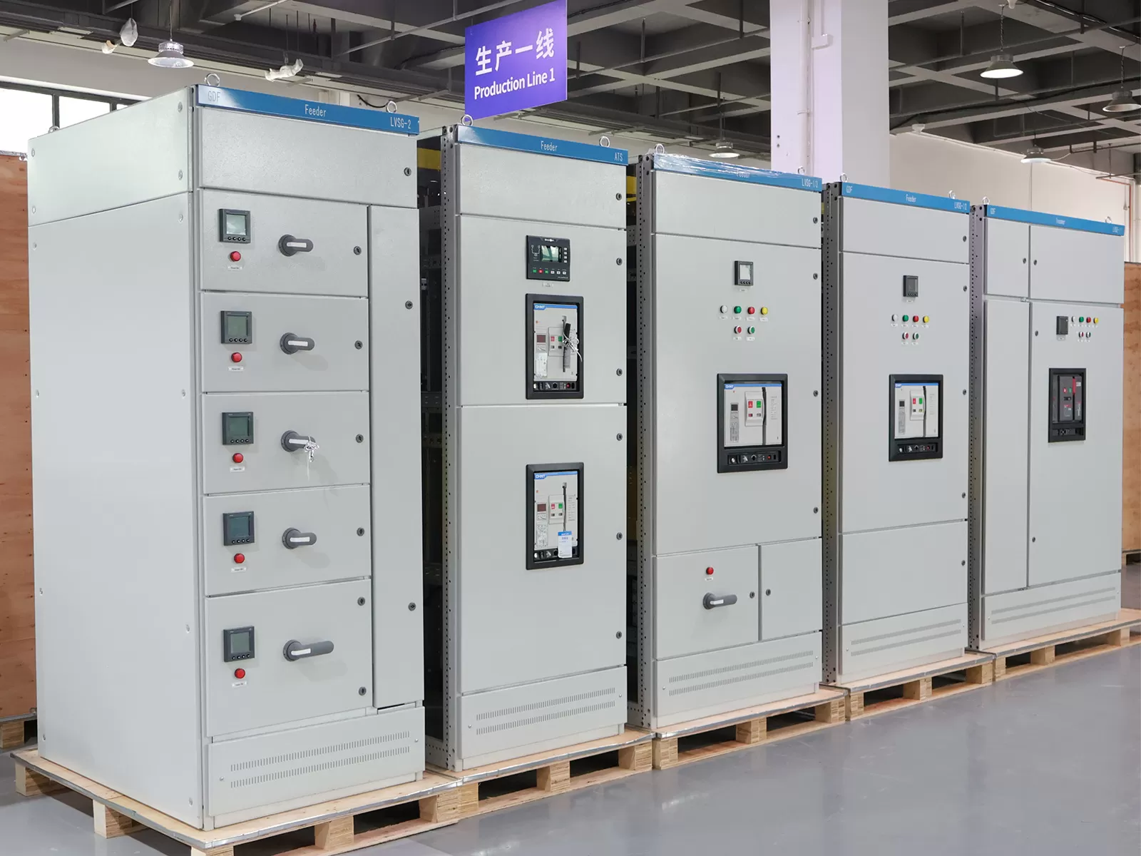
Regulatory Standards and Mechanical Boundaries: IEC 61439 vs. UL 891
Electrical safety and operational predictability depend largely on alignment with established international frameworks. Global industrial projects typically navigate two dominant testing and design regimes: the IEC 61439 series (specifically IEC 61439-1 and IEC 61439-2) across Europe, Asia-Pacific, and the Middle East, and UL 891 throughout North America. Understanding the structural and electrical differences between these standards prevents costly redesigns and site-acceptance failures.
IEC 61439-2 replaced the older concept of type-tested assemblies (TTA) and partially type-tested assemblies (PTTA) with a design verification methodology. Manufacturers must confirm assembly performance through laboratory testing, calculation, or adherence to strict design rules across thirteen specific verifications, including:
- Strength of materials and resistance to corrosion in aggressive industrial environments.
- Degree of protection against mechanical impacts (IK rating) and water or dust ingress (IP rating up to IP54 or IP65).
- Clearance and creepage distances determined by pollution degree, overvoltage category, and rated impulse withstand voltage (Uimp).
- Dielectric properties verified through power-frequency withstand voltage testing.
- Short-circuit withstand strength (Icw and Ipk) under prospective maximum fault conditions.
- Electromagnetic compatibility (EMC) compliance for environments with high high-frequency noise from variable frequency drives.
UL 891, the benchmark standard for dead-front distribution assemblies in North America, specifies mechanical construction, busbar bracing tolerances, and dielectric testing procedures tailored to National Electrical Code (NEC/NFPA 70) parameters. Unlike international designs centered heavily on internal separation classifications, UL 891 emphasizes standardized horizontal and vertical busbar spacing, accessibility parameters for pull boxes, and specific heat run testing criteria calculated under ambient conditions up to 40 degrees Celsius.
Engineering teams frequently evaluate international plant expansions requiring dual-compliance considerations. When commissioning an industrial switchboard, structural integrity under high magnetic stresses caused by short-circuit faults requires validated design verification data rather than empirical approximations.
Internal Compartmentalization and Forms of Separation
Segregation within electrical enclosures protects operators from accidental contact with energized parts and limits the propagation of internal faults between distinct functional units. Under IEC 61439-2, this mechanical segregation is classified into defined Forms of Separation ranging from Form 1 through Form 4b.
- Form 1: Offers no internal separation between busbars, functional units, or termination points. External enclosure protection is the only mechanical barrier.
- Form 2 (2a and 2b): Separates the main busbars from the functional units. In Form 2b, the outgoing terminals are also separated from the main busbar assembly, reducing risk during routine inspection of outgoing cabling.
- Form 3 (3a and 3b): Provides separation between busbars and individual functional units, while separating the functional units from one another. Outgoing terminal blocks remain grouped within a common wiring space.
- Form 4 (4a and 4b): Represents the highest level of segregation. Busbars are separated from functional units, all functional units are isolated from one another, and outgoing terminals for each functional unit are enclosed in dedicated, individual compartments. In Form 4b, cable termination points reside in completely distinct compartments away from the functional units they feed.
For high-availability automated manufacturing lines, Form 4b provides critical operational benefits. Maintenance personnel can safely work within an outgoing terminal chamber or replace a withdrawable circuit breaker without isolating adjacent functional circuits or exposing personnel to the energized main distribution bus.
Busbar Topologies, Electrodynamic Forces, and Thermal Dissipation
The electrical spine of any distribution equipment consists of its busbar assembly. Industrial facilities operating high-tonnage stamping presses, multi-axis automated lines, and heavy induction equipment subject their distribution assemblies to dynamic load changes and intermittent fault potentials. Specifying busbar geometry requires balancing thermal dissipation against the electromechanical stresses that occur during a short-circuit event.
Electrodynamic forces between parallel conductors during a prospective short-circuit fault are proportional to the square of the peak current (Ipk) and inversely proportional to the spacing between the conductors. When a three-phase bolted fault occurs, conductors experience massive mechanical repulsion or attraction forces within the first quarter-cycle. Busbar supports made of glass-reinforced polyester or cycloaliphatic resins must withstand these forces without mechanical deflection or tracking breakdown.
Copper conductors conforming to electrolytic tough pitch specifications (Cu-ETP, minimum 99.9% purity) offer optimal electrical conductivity and mechanical yield strength. In high-humidity or chemically aggressive environments, tin or silver plating prevents surface oxidation and preserves low-resistance joints. Engineering teams like XDEPE address these electrodynamic constraints through structural bracing analysis and thermodynamic modeling to ensure busbar systems resist mechanical deflection while maintaining optimal surface temperatures under full load.
Thermal management inside the enclosure presents a secondary challenge. Enclosure configurations must dissipate joule losses ($I^2R$) generated across circuit breakers, disconnects, busbar joints, and cable terminations. In high IP-rated enclosures (such as IP54 for dusty plant floors), convective cooling is limited. Engineers calculate temperature-rise limits according to IEC standards, ensuring terminal connections do not exceed standard design thresholds (typically a 70 Kelvin rise above ambient for bare copper terminals) to prevent premature insulation failure.
Harmonics, Power Quality, and Arc Flash Mitigation
Automated manufacturing environments rely heavily on non-linear loads, including variable frequency drives (VFDs), servo controllers, automated welding cells, and switched-mode power supplies. These loads generate significant harmonic distortion, especially 5th, 7th, 11th, and 13th harmonic orders. Triplen harmonics (3rd, 9th, 15th) circulate through neutral conductors, causing overheating in four-pole distribution topologies if neutral cross-sections are undersized.
Harmonic currents cause eddy-current and skin-effect losses within busbars, increasing operative temperatures beyond standard line-frequency baseline projections. Mitigating these risks requires oversized neutral conductors (often 200% of phase cross-section), active harmonic filters, and detuned capacitor banks integrated directly into the distribution layout.
Beyond harmonic distortion, arc flash hazards represent the most dangerous risk to plant safety and continuous production. An arcing fault releases explosive kinetic and thermal energy within milliseconds, vaporizing copper and generating pressure waves that destroy mechanical equipment. Comprehensive mitigation requires combining passive and active protection systems:
- Internal Arc Classification (IAC): Enclosures tested in accordance with IEC TR 61641 direct arc gases away from operators through pressure relief flaps and dedicated exhaust plenums.
- Optical Arc Detection: Fiber-optic point sensors or bare-fiber line sensors detect the optical flash of an arc within 1 to 2 milliseconds, immediately sending a trip signal to main incomer breakers equipped with low-latency shunt trips.
- Arc Quenching Devices: Ultra-fast pyrotechnic or electromagnetic grounding switches intentionally drive the system into a controlled bolted three-phase fault, diverting arc current away from air-insulation gaps and clearing the fault within 4 to 5 milliseconds.
- Zone Selective Interlocking (ZSI): Upstream and downstream digital trip units communicate via hardwired data channels. If a downstream breaker detects a fault, it signals upstream devices to delay tripping, localizing the interruption to the faulted circuit without shutting down the entire plant.
Digital Transformation: Industrial Automation and Communications Protocols
Modern electrical engineering links power management directly with supervisory control. Incorporating digital intelligence into the physical switchboard enables real-time asset health diagnostics, predictive maintenance, and energy management without relying solely on manual operational logs.
Intelligent low-voltage assemblies feature microprocessor-based trip units, power quality meters, and distributed input/output modules connected over robust fieldbuses. Industrial communication architectures must bridge the physical isolation between low-voltage compartments and plant-wide control networks:
- IEC 61850: Originally established for high-voltage substations, IEC 61850 is increasingly applied in industrial power systems, leveraging Generic Object Oriented Substation Events (GOOSE) messaging for ultra-fast protective interlocking over Ethernet.
- Modbus TCP / RTU: The established baseline for energy monitoring, telemetry, and secondary alarming within standard SCADA packages.
- PROFINET and EtherNet/IP: Preferred protocols when power distribution subsystems interface directly with manufacturing execution systems (MES) and primary PLC lines controlling industrial automation equipment.
During the automation design phase, XDEPE assists system integrators in mapping physical field signals to digital fieldbus topologies, ensuring communication interfaces are isolated from electromagnetic interference generated by adjacent high-current interruptions.
Digital assemblies also integrate thermal monitoring networks. Fiber-optic temperature probes or wireless infrared surface sensors mounted on primary busbar joints and breaker stabs track localized temperature changes. Because these sensors log real-time data, control systems can flag abnormal thermal trends caused by loose bolts or surface oxidation weeks before catastrophic insulation failure occurs.
Procurement Frameworks, Factory Acceptance, and Quality Assurance
Purchasing large-scale electrical infrastructure requires rigorous technical due diligence. Low upfront procurement bids often conceal design shortcuts, such as reduced copper cross-sections, lower-grade insulator plastics, or limited separation barriers, which lead to higher maintenance costs over time.
Procurement teams should base evaluation matrices on structural, electrical, and commercial parameters:
- Type Testing Pedigree: Require complete third-party type-test certificates from accredited laboratories (such as ASTA, KEMA, or UL) matching the specific internal configuration, frame size, and short-circuit rating quoted by the vendor.
- Modularity and Extensibility: Ensure the mechanical frame allows future expansion on both ends without requiring total busbar re-engineering or structural cutting.
- Withdrawable vs. Fixed Execution: For critical 24/7 continuous manufacturing plants, withdrawable circuit breakers and motor starter buckets allow rapid component replacement without shutting down adjacent line sections.
- Component Neutrality: Evaluate whether internal mounting hardware supports open-market breaker components or locks the facility into sole-source proprietary replacement parts.
Factory Acceptance Testing (FAT) serves as the primary verification checkpoint before site delivery. A rigorous FAT protocol should include:
- Mechanical operation checks of all interlocks, withdrawable mechanisms, and door latching hardware.
- High-potential (Dielectric) testing at designated power-frequency test voltages to verify clearances and insulation integrity.
- Insulation resistance measurements taken before and after dielectric stress testing using a calibrated 1000V megohmmeter.
- Verification of wiring correctness against approved schematics, including secondary control loops, CT polarity, and digital bus addressing.
- Torque verification of structural and busbar joint fasteners, confirmed by torque-seal paint marks.
Comprehensive verification protocols ensure that each fabricated switchboard meets site-specific dynamic fault ratings and integrates smoothly into existing plant automation platforms.
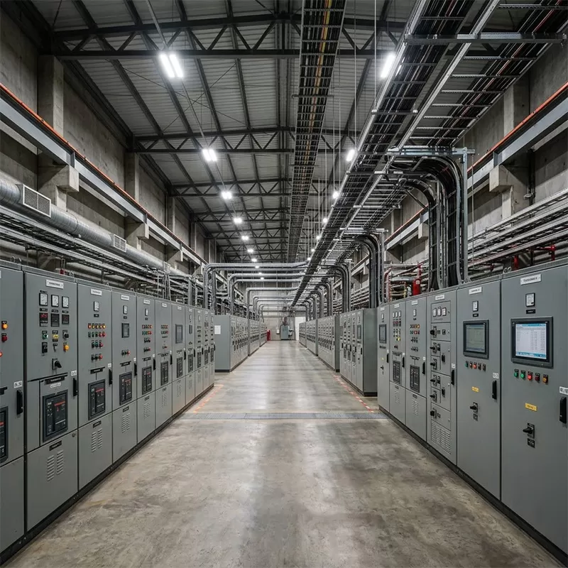
Preventive Maintenance, Diagnostics, and Asset Preservation
Maintaining power distribution reliability requires disciplined preventive and predictive maintenance strategies. While modern equipment is engineered for extended service intervals, industrial dust, vibration from stamping machinery, ambient thermal cycling, and chemical contaminants degrade components over time.
Thermographic inspections using infrared cameras should be conducted under normal to peak operating loads at six-month intervals. Thermal anomalies typically trace back to loose bolted joints, improper contact pressure on circuit breaker disconnect fingers, or unbalanced phase distribution. Any joint showing a temperature rise greater than 10 degrees Celsius above adjacent phases requires immediate physical inspection and re-torquing during the next scheduled plant shutdown.
Circuit breaker servicing must adhere strictly to original equipment manufacturer guidelines. Air Circuit Breakers (ACBs) require scheduled cleaning of arc chutes, inspection of main and arcing contacts for erosion, lubrication of operating mechanisms with manufacturer-approved synthetic greases, and secondary injection testing of electronic trip units to verify pickup values and delay curves match engineering coordination studies.
Molded Case Circuit Breakers (MCCBs) require routine insulation resistance testing and mechanical cycling. In environments exposed to heavy vibration, periodic ultrasonic testing helps detect micro-fissures in structural supports or early-stage partial discharge phenomena within medium-to-low voltage step-down connections.
Frequently Asked Questions
Q1: What is the primary functional difference between Form 2b and
Form 4b internal separation?
A1: Form 2b separates the main busbars
from functional units and terminal blocks, but functional units and their
outgoing terminals share common internal spaces. Form 4b isolates every
functional unit from all other units and places outgoing cable termination
points into completely distinct, individual compartments, allowing personnel to
safely land field cables without exposure to energized components on adjacent
circuits.
Q2: Why are non-linear loads in automated manufacturing dangerous to
distribution busbars?
A2: Non-linear loads produce harmonic currents
that do not cancel out in the neutral conductor, causing elevated neutral
currents that can reach up to 173% to 200% of phase current. Additionally,
higher frequencies increase conductor resistance via the skin effect and induce
eddy-current losses in enclosure steel, accelerating insulation degradation
through excessive heat.
Q3: How does active arc flash protection differ from passive blast
containment?
A3: Passive blast containment relies on reinforced
doors, heavy latches, and internal pressure exhaust ducts to direct explosive
arc gases safely away from personnel during a fault. Active arc flash protection
uses optical sensors and electrical thresholds to trip upstream breakers or
trigger fast-acting grounding switches within milliseconds, extinguishing the
fault before high arc energy and pressure can develop.
Q4: What key parameters determine the required short-circuit
withstand rating (Icw)?
A4: The rated short-time withstand current
(Icw) depends on the available prospective fault current from upstream
transformers and on-site generation, the impedance of the interconnecting cable
or busway run, and the clearing time of upstream protective devices. The
assembly must handle this mechanical and thermal energy for a set duration
(typically 1.0 or 3.0 seconds) without mechanical deformation or insulation
failure.
Q5: Can existing low-voltage power assemblies be updated to
industrial Ethernet without complete replacement?
A5: Yes. Many
legacy installations can be modernized by retrofitting smart electronic trip
units on existing air circuit breakers, installing external communication
bridges that convert Modbus RTU serial data to Industrial Ethernet (such as
PROFINET or Modbus TCP), and mounting non-invasive wireless temperature and
current sensors on primary bus joints.
Engineering Consultation and Project Implementation
Configuring a dependable power infrastructure requires balancing complex electromechanical demands, plant automation standards, and strict workplace safety rules. Contact the technical engineering group at XDEPEto review project specifications, evaluate fault-current mitigation options, and design customized power distribution assemblies built for the demanding conditions of modern industrial manufacturing.




 Cabinet (1).webp "Automatic Transfer Switch (ATS) Failure: 5 Common Causes and How to Fix Them")
.webp "How to Select the Right 3 Phase Panel Board for Heavy Manufacturing Equipment")
 Switchgear (1).webp "What is a Withdrawable (Drawer-Type) Switchgear? A Complete Beginner's Guide")
.webp "Main Distribution Board vs. Sub Main Distribution Board: What's the Difference & How to Choose?")
