
Electric power infrastructure within automated manufacturing environments has transitioned from passive branch circuits into active, telemetry-enabled control ecosystems. Automated production lines, robotic cells, and high-throughput packaging environments demand continuous power delivery free from voltage sags, phase imbalances, and harmonic distortion. At the center of this interface stands the distribution panel board, functioning as the primary junction between high-capacity incoming substations and downstream operational technology. Designing, specifying, and deploying these assemblies requires a deep reconciliation between classical electrical engineering principles and the telemetry demands of Industry 4.0.
Modern production facilities rely on heavy cyclical loads driven by variable frequency drives (VFDs), servo systems, heating elements, and high-frequency welding machines. These dynamic loads introduce non-linearities and thermal stresses that can compromise poorly engineered switchgear assemblies. Consequently, industrial plant managers and electrical design engineers must look beyond basic ampacity ratings when selecting distribution apparatus, prioritizing short-circuit withstand capabilities, internal compartmentalization, harmonic mitigation, and field-bus communication networks.
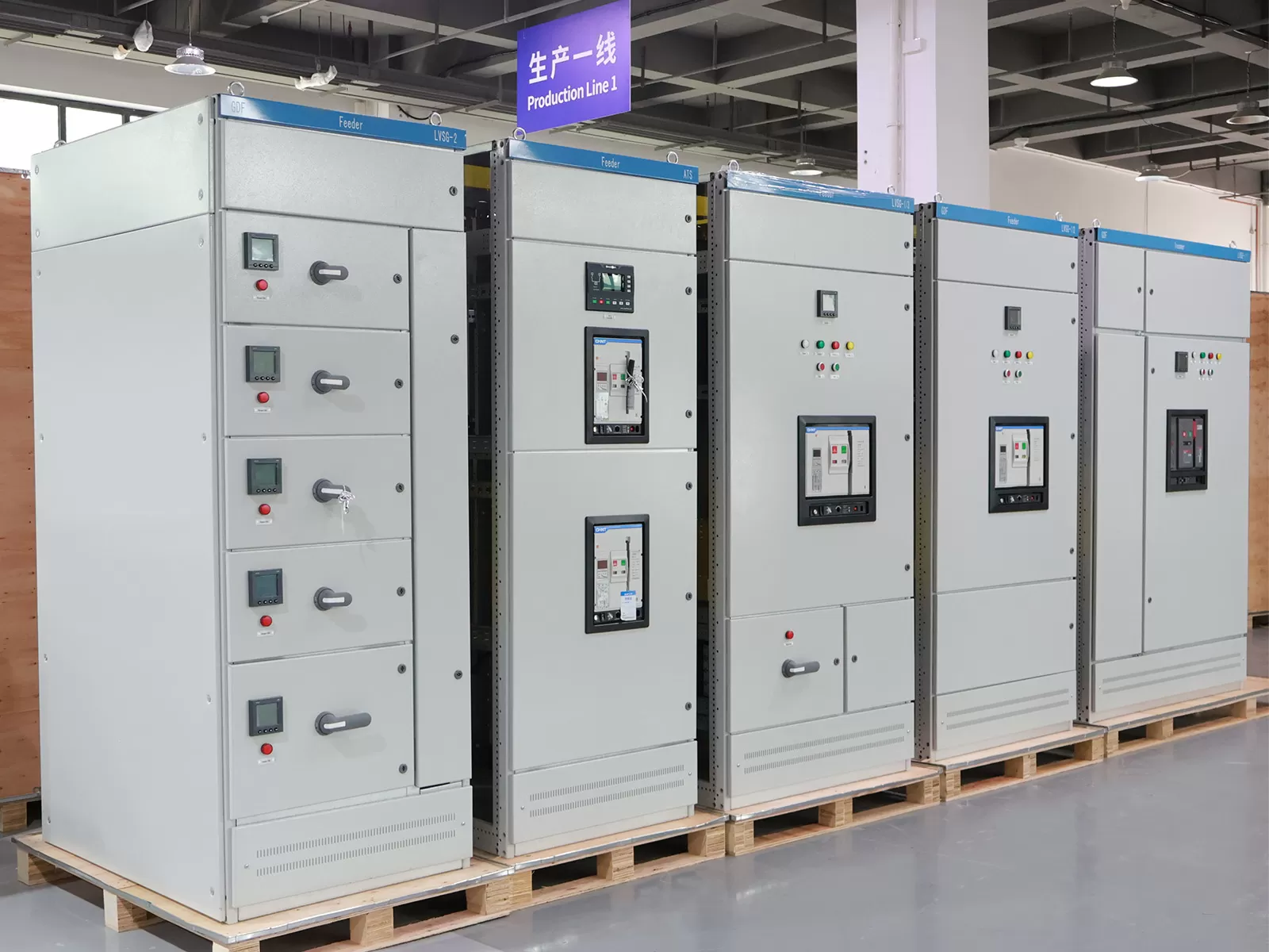
Topologies and Internal Segregation in Manufacturing Environments
Automated facilities cannot tolerate unscheduled shutdowns caused by internal fault propagation. A single arcing event inside a general-purpose enclosure can instantly halt upstream feeder lines, causing cascading downtime across multiple work cells. Industrial electrical enclosures mitigate this threat by adopting rigid structural topologies and internal physical boundaries.
Enclosure architecture relies fundamentally on internal separation classifications defined by standards such as IEC 61439-2. These internal divisions, ranging from Form 1 to Form 4b, dictate the degree of physical barrier isolation established between the horizontal/vertical busbars, functional switching units (breakers, disconnects), and outgoing cable termination terminals.
Form 1: Offers no internal separation. Busbars, functional units, and terminals reside within a single shared space. This arrangement is generally limited to low-risk auxiliary control spaces.
Form 2 (2a, 2b): Segregates the busbars from the operational functional units. Form 2b further isolates the termination points from the main busbar assembly, protecting technicians during line inspections.
Form 3 (3a, 3b): Isolates the busbars from functional units while simultaneously separating individual functional units from one another. Outgoing terminals are either shared or segregated, preventing faults in one motor branch circuit from destroying adjacent switchgear.
Form 4 (4a, 4b): Provides complete compartmentalization. The busbars are isolated from functional units; individual functional units are isolated from each other; and the termination points for each individual circuit are strictly segregated. Form 4b architectures represent the gold standard for continuous process plants, allowing maintenance teams to service a branch breaker without de-energizing adjacent active circuits.
Busbar design requires careful mechanical calculation. Solid copper busbars, typically electrolytic tough pitch (ETP) copper with tin or silver plating, must be sized according to continuous current ratings and dynamic electrodynamic forces generated during prospective short circuits. Under peak fault currents (Ipk), phase conductors experience massive repulsive magnetic forces. The mechanical support insulators, manufactured from glass-reinforced polyester or cycloaliphatic epoxy, must withstand these lateral stresses without fracturing, maintaining the specified creepage and clearance distances across the operational envelope.
Short-Circuit Ratings, Selectivity, and Protection Coordination
Fault mitigation within manufacturing facilities requires an engineered protective device chain. The prospective short-circuit current (Icp) at the installation point determines the required short-circuit withstand rating (SCCR) and interrupting capacity of the distribution equipment. Modern automation systems cannot rely on bulk tripping mechanisms; instead, they necessitate total selective coordination across upstream and downstream protective devices.
Selective coordination ensures that when a localized overcurrent or ground fault occurs—such as a shorted winding on a conveyor drive—only the protective device immediately upstream of the fault clears the condition. Upstream feeder breakers and main incoming switchgear remain closed, preserving continuous power for the rest of the facility. Achieving this level of discrimination requires an exhaustive study of time-current curves (TCCs), fault energy release curves (I²t characteristics), and peak let-through energy levels.
| Protection Parameter | Primary Engineering Consideration | Impact on Automation Uptime |
|---|---|---|
| Short-Circuit Withstand (Icw) | Thermal and electrodynamic capacity of the busbar system over a specific duration (typically 1.0s or 3.0s). | Prevents mechanical destruction of the internal structural bus during high-magnitude upstream clearing intervals. |
| Short-Circuit Breaking Capacity (Icu/Ics) | Ultimate and operational breaking capacity of the molded case (MCCB) or air circuit breaker (ACB). | Ensures the breaker can repeatedly clear severe industrial fault currents without catastrophic failure or dielectric breakdown. |
| Time-Current Discrimination (I²t) | Calibrated delay profiles (LSI/LSIG curves) programmed into electronic trip units. | Isolates faults exclusively to the affected machine sector, eliminating plant-wide line halts. |
| Arc Flash Mitigation | Implementation of optical arc sensors, energy-reducing maintenance switches (ERMS), and fast-acting zone interlocking. | Protects plant personnel during diagnostic routines and prevents enclosure rupture during arc blast conditions. |
Transient overvoltages represent another frequent threat to industrial automation circuits. Switching inductive equipment, engaging dynamic braking resistors, and lightning strikes propagate steep-front surges across the electrical distribution board. Integrating Type 1 and Type 2 Surge Protective Devices (SPDs) directly into the primary bus section suppresses these spikes, clamping transient voltages down to levels compatible with sensitive PLC microcontrollers, digital I/O modules, and field transducers.
Harmonic Mitigation and Power Quality in Automated Workcells
Automated plants operate hundreds of non-linear loads. Pulse-width modulated (PWM) AC drives, DC rectifiers, robotic power supplies, and switch-mode converter circuits generate harmonic currents at frequencies that are integer multiples of the fundamental grid frequency (50/60 Hz). Fifth, seventh, eleventh, and thirteenth harmonics circulate back into the distribution network, creating thermal, dielectric, and electromagnetic challenges.
Triplen harmonics (specifically the 3rd and 9th orders) do not cancel out in the neutral conductor; they add arithmetically. In automated facilities with high single-phase switch-mode power supply densities, the neutral busbar can carry currents that equal or exceed the phase current magnitude. Specifying an oversized neutral conductor—often rated at 200% of the phase busbar—prevents neutral conductor burnout. Technical teams, including the engineering specialists at XDEPE, routinely account for these harmonic derating multipliers when laying out custom distribution architectures for heavy industrial automation.
Mitigating harmonic propagation directly within the industrial panel board involves several complementary engineering strategies:
Tuned Passive Harmonic Filters: LC circuits connected in parallel with the main load centers, tuned specifically to absorb 5th and 7th harmonic frequencies, thereby reducing total harmonic current distortion (THDi).
Active Power Filters (APFs): Advanced power electronic devices using insulated gate bipolar transistors (IGBTs) to inject anti-phase compensation currents into the line in real-time, effectively cancelling dynamic harmonics across a wide frequency spectrum up to the 50th order.
K-Factor and Harmonic-Rated Isolation Transformers: Step-down transformers engineered to withstand the eddy current losses and stray load losses induced by harmonic currents, preventing core saturation and thermal runaway.
Phase-Shifting Transformer Configuration: Employing dual-converter feeds with delta-wye configurations to achieve quasi-12-pulse or 18-pulse cancellation profiles directly at the power intake stage.
Integrating Smart Switchgear with SCADA and Industrial Networks
The transformation of modern manufacturing has elevated the distribution panel board from an isolated steel cabinet to an intelligent industrial node. Electrical distribution networks are now woven into supervisory control and data acquisition (SCADA) platforms, manufacturing execution systems (MES), and enterprise energy management suites via high-speed, deterministic industrial Ethernet and fieldbus networks.
Microprocessor-controlled trip units and digital multi-function meters provide granular data acquisition directly at each feeder branch. Electrical parameters monitored in real-time include per-phase root-mean-square (RMS) current, true RMS voltage, active and reactive power, power factor, crest factor, and individual harmonic distortion levels up to the 63rd harmonic. By converting raw physical values into protocol-compliant packets (such as Modbus TCP/IP, Profinet, or EtherNet/IP), the panel board provides continuous telemetry regarding machine operational health.
Predictive maintenance capabilities rely heavily on these internal digital sensors. When a mechanical bearing on a major conveyor drive begins to degrade, the drive motor draws asymmetrical currents and exhibits unique load fluctuations. Intelligent branch circuits detect these sub-millisecond current signature variations long before an overtemperature alarm activates. Automation engineers can correlate power draw spikes with specific cycle states of automated tooling machines, identifying mechanical wear, tooling dullness, or valve sticking without physical line intervention.
Furthermore, internal physical thermal monitoring has shifted toward contactless continuous sensing. In lieu of periodic infrared thermographic inspections performed by external contractors, modern panel board architectures embed non-contact infrared thermal sensors or optical fiber temperature arrays directly along primary busbar joints, breaker terminal stabs, and high-current cable lugs. This telemetry streams to plant management systems, providing instant warning if a loose bolt torque or surface oxidation induces localized I²R heating.
Thermal Dynamics and Environmental Protection
Power losses within an industrial distribution board translate directly into heat dissipation within an enclosed steel volume. Circuit breakers, fuses, busbar joints, and instrumentation power supplies all contribute to internal heat load. If heat is not removed systematically, internal ambient temperatures can easily exceed the 40°C design baseline, triggering nuisance breaker tripping, premature aging of conductor insulation, and catastrophic failure of microelectronic control modules.
Design teams calculate heat dissipation using thermodynamic equilibrium models:
Q_total = Q_switchgear + Q_busbars + Q_cables + Q_accessories
The rate of internal temperature rise depends upon the external surface area of the enclosure, the thermal heat transfer coefficient of the enclosure material, and the operational ambient temperature of the plant floor. In light industrial spaces, natural convection cooling through engineered louvers and dust filters may suffice. However, automated manufacturing facilities often subject equipment to harsh environmental airborne particulate matter, metal shavings, cutting fluids, high humidity, or wash-down procedures.
These environments require sealed enclosures manufactured to precise protection classes, such as IP54, IP65, or NEMA 4/4X. When an enclosure is completely sealed to prevent the ingress of liquid and airborne contaminants, natural convection cooling fails. Engineers must install closed-loop cooling systems, such as panel-mounted air conditioners or air-to-water heat exchangers. Closed-loop systems isolate the internal air cycle from contaminated factory air, extracting heat while actively maintaining internal relative humidity below the dew point, preventing destructive condensation cycles during rapid factory temperature shifts.
Procurement Specifications and Engineering Standards
Procurement teams, plant electrical engineers, and original equipment manufacturers (OEMs) must navigate a complicated matrix of international standards when sourcing distribution equipment. A misaligned specification can delay project commissioning, invalidate factory insurance, or introduce severe occupational hazards.
Global operations typically adhere to two dominant regulatory frameworks: the IEC (International Electrotechnical Commission) framework, prevailing throughout Europe, Asia, and the Middle East, and the UL/NEMA framework, dominant across North America.
IEC 61439-1 and -2: Defines the requirements for low-voltage switchgear and controlgear assemblies. It supersedes older "type-tested" and "partially type-tested" terminology with a strict verification regime encompassing 13 separate design tests, including temperature rise limits, dielectric properties, short-circuit withstand strength, protective circuit continuity, and mechanical operation verification.
UL 891 and UL 67: Cover switchboards and panelboards within the North American sphere. These standards dictate precise wire-bending spaces, metal thickness, creepage and clearance metrics, and overcurrent device integration tested in accordance with the National Electrical Code (NEC / NFPA 70).
When preparing equipment bids, procurement engineers must clarify detailed parameters within their technical datasheets rather than issuing broad, generic requests. Critical specifications include nominal operational voltage (Ue), rated insulation voltage (Ui), rated impulse withstand voltage (Uimp), prospective short-circuit current at the incoming terminals, specific Form of separation, ingress protection code, and harmonic conditions.
Procurement strategies must also factor in long-term expansion capacity. Specifying a distribution assembly with 25% to 30% unequipped space—complete with pre-drilled busbar extensions and modular DIN rail bays—substantially reduces total cost of ownership (TCO). When an automated facility incorporates new manufacturing cells, technicians can insert additional branch protective units without rebuilding the entire power distribution backbone. Organizations like XDEPE assist industrial engineering departments by configuring modular, expandable switchgear architectures that account for projected multi-year plant floor expansions.
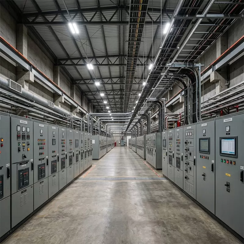
Field Commissioning, Verification, and Lifecycle Management
Transitioning an engineered electrical panel from the factory floor to live manufacturing requires structured validation. Mechanical, structural, and electrical integrity must be verified through strict Factory Acceptance Testing (FAT) and subsequent Site Acceptance Testing (SAT).
Prior to energization, the commissioning protocol mandates a comprehensive sequence of physical and electrical checks:
Insulation Resistance Testing (Megger): Conductors must be tested using a high-voltage DC supply (typically 500V or 1000V DC) phase-to-phase, phase-to-neutral, and phase-to-earth. Baseline readings should significantly exceed nominal manufacturer thresholds (typically >100 Megaohms) to confirm no insulation shearing occurred during field cable pulling.
Contact Resistance Testing (Ductor / Micro-Ohmmeter): High-current low-resistance testing measures the millivolt drop across busbar splices, breaker stabs, and mechanical disconnect joints. Elevated resistance values pinpoint improperly torqued fasteners or surface contamination that would inevitably produce thermal hotspots during full-load operation.
Dielectric Withstand Testing (Hi-Pot): Verifies that the internal clearances, creepage distances, and solid insulation materials can survive high-voltage transient spikes without breakdown.
Secondary Injection Testing: Electronic trip units are tested using specialized test sets to inject synthetic current profiles directly into the solid-state trip brains, verifying that the programmed LSI coordination parameters match the plant's engineered protection study.
Torque Verification: All structural and electrical bolted joints must be verified with calibrated torque wrenches against the manufacturer's specified tightening tables, accompanied by torque seal paint marking for visual inspection.
Throughout operational life, preventive maintenance must be replaced by condition-based maintenance. Automated plants cannot sustain biannual de-energization for routine checks. By utilizing continuous telemetry, real-time thermal sensors, and periodic ultrasonic testing (which detects partial discharge phenomena before visible tracking damage occurs), facility operators keep critical equipment functioning reliably over decades of rigorous manufacturing cycles.
Technical Frequently Asked Questions
Q1: How is the Short-Circuit Withstand Rating (SCCR) determined for
an industrial assembly, and why can it not be increased by simply upsizing the
downstream breakers?
A1: The overall SCCR of an integrated assembly
is strictly determined by its lowest-rated component or its tested
series-combination rating. You cannot raise the rating simply by swapping branch
breakers, because the physical structural busbars, terminal blocks, disconnect
switches, and internal wiring harnesses must all be mechanically and thermally
rated to withstand the identical prospective fault current energy. If an
incoming terminal block has an SCCR of 10kA, the entire panel rating drops to
10kA, regardless of whether the branch breakers possess individual interrupting
ratings of 65kA, unless a tested current-limiting device is placed upstream to
limit peak let-through current.
Q2: What is the practical engineering distinction between Form 3b and
Form 4b internal separation?
A2: Both Form 3b and Form 4b
configurations isolate the main busbars from the functional units (breakers) and
isolate the functional units from each other. The core operational distinction
lies in how the outgoing cable termination terminals are handled. In Form 3b,
the termination points for external field cables are kept in a separate terminal
compartment, but the terminals for multiple circuits can share that common
space. In Form 4b, the outgoing terminals for each individual functional unit
are completely separated from the terminals of any other unit inside their own
distinct, physical compartments. Form 4b allows a technician to work safely
inside the termination area of one isolated circuit while the neighboring
circuits remain completely energized and operational.
Q3: How does high harmonic distortion impact the sizing of neutral
busbars in automated plants?
A3: Non-linear loads—such as
single-phase switch-mode power supplies, PLCs, and variable speed drive input
stages—generate zero-sequence triplen harmonics (3rd, 9th, 15th, etc.). Unlike
fundamental 50/60 Hz balanced three-phase currents that cancel out to zero in
the neutral conductor, triplen harmonic currents add up constructively in the
neutral path. Under heavy non-linear loading conditions, neutral currents can
reach up to 140% to 175% of the phase conductor currents. If the neutral bus is
sized at the standard 50% or 100% of phase ampacity, it will experience chronic
overheating and catastrophic insulation failure. Industrial automation systems
frequently require the neutral busbar to be specified at 200% capacity to safely
dissipate these circulating currents.
Q4: Under what operational conditions should an industrial panel
board transition from passive convection louvers to closed-loop climate
control?
A4: Passive cooling (convection louvers or ventilation
fans) is acceptable only when the ambient external environment is clean,
non-corrosive, non-conductive, and consistently at least 5°C to 10°C lower than
the internal design temperature of the cabinet. Closed-loop active air
conditioning or heat exchangers must be specified when the environment contains
airborne contaminants (conductive carbon dust, metallic chips, airborne oils,
chemical fumes), when the enclosure must maintain an IP54, IP65, or NEMA 4/12
rating to protect sensitive electronics, or when external factory temperatures
fluctuate above the maximum allowable internal thermal limit.
Q5: What is the operational difference between the Icu and Ics
ratings specified on industrial circuit breakers?
A5: Both ratings
reflect short-circuit performance under the IEC 60947-2 standard. Icu (Ultimate
Short-Circuit Breaking Capacity) represents the maximum fault current magnitude
the circuit breaker can safely interrupt twice (an Open-Close/Open test
sequence) without exploding or igniting, but the breaker is not required to
maintain operational functionality afterward. Ics (Service Short-Circuit
Breaking Capacity) represents the fault level the breaker can interrupt
repeatedly while remaining fully operational, continuing to carry continuous
nominal current and clear future overcurrents without out-of-tolerance
dielectric degradation. In high-reliability automated facilities, engineers
should mandate an Ics rating equal to 100% of the Icu (Ics = 100% Icu) to ensure
the breaker does not require replacement after clearing a typical fault
event.
Engineering Advisory and Project Specifications
Selecting, laying out, and implementing an automated distribution panel board architecture requires an exact balance between thermodynamic realities, fault-clearing precision, mechanical robustness, and industrial communication standards. Whether designing a greenfield automated manufacturing plant or retrofitting legacy infrastructure to meet the telemetry demands of smart manufacturing, the engineering specialists at XDEPE collaborate with project managers, systems integrators, and plant electrical directors to deliver structurally verified, fully coordinated power distribution solutions engineered to exact project requirements.
To discuss your automation layout, request bespoke design assistance, or submit single-line diagrams (SLDs) for engineering review, contact the technical integration team: yoyo@xdepe.com



 Cabinet (1).webp "Automatic Transfer Switch (ATS) Failure: 5 Common Causes and How to Fix Them")
.webp "How to Select the Right 3 Phase Panel Board for Heavy Manufacturing Equipment")
 Switchgear (1).webp "What is a Withdrawable (Drawer-Type) Switchgear? A Complete Beginner's Guide")
.webp "Main Distribution Board vs. Sub Main Distribution Board: What's the Difference & How to Choose?")
