
Automated manufacturing environments rely on uninterrupted electrical stability. High-speed assembly lines, multi-axis robotic cells, and continuous process control systems require power distribution infrastructure capable of handling dynamic, non-linear loads without voltage sags or localized thermal runaway. Central to this electrical infrastructure sits the mains board, serving as the foundational nexus between incoming utility feeds or medium-voltage transformation steps and downstream plant machinery. Specifying this equipment demands rigorous attention to fault current tolerance, thermal management, harmonic mitigation, and data connectivity, transforming conventional electrical distribution into an active participant in operational resilience.
Modern electrical engineering has elevated low-voltage assemblies from passive structural enclosures to sophisticated platforms integrated with digital intelligence. When automation machinery shifts loads abruptly—such as during simultaneous servo acceleration or large induction motor startups—the incoming distribution infrastructure absorbs the mechanical and thermal stress. The engineering of the internal components, busbar geometries, and circuit protection devices determines whether a facility achieves maximum Mean Time Between Failures (MTBF) or suffers catastrophic line shutdowns.
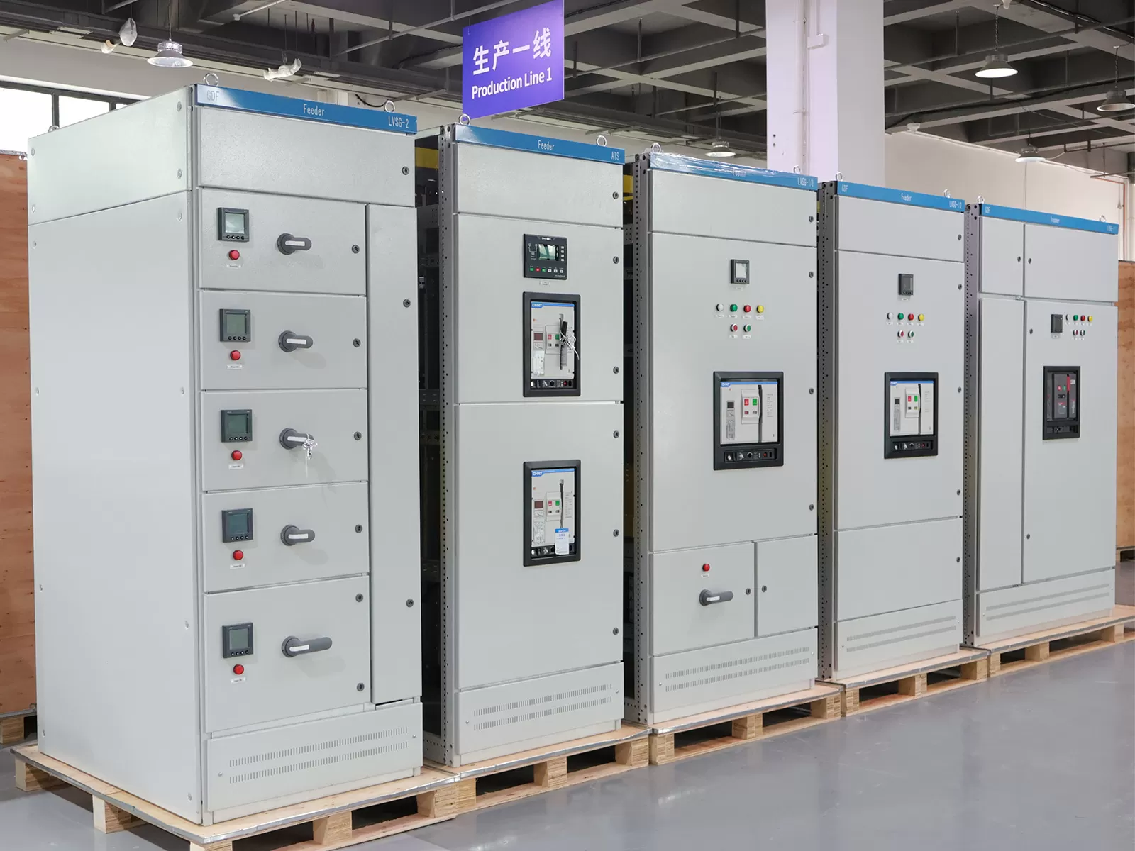
Electromechanical Topology and Busbar Dynamic Withstand
The primary function of any industrial-scale mains board is to accept incoming bulk electrical energy and distribute it across segregated functional units while withstanding both steady-state thermal loads and prospective short-circuit stresses. Designing these systems requires calculating the prospective short-circuit current (Icp) and establishing the rated short-time withstand current (Icw) alongside rated peak withstand current (Ipk) in strict compliance with IEC 61439-1 and IEC 61439-2.
During a bolted three-phase fault, electrodynamic forces between parallel conductors scale with the square of the instantaneous peak current. Busbar supports must be mechanically engineered using high-strength, glass-reinforced polyester or cycloaliphatic epoxy materials. These supports prevent conductor deflection, phase-to-phase flashover, and structural chassis shearing. Conductor geometries, whether flat copper bar, profiled copper, or treated aluminum composites, dictate current density parameters and skin-effect losses at fundamental and harmonic frequencies.
Phase busbars must be rated according to maximum ambient temperatures inside the cubicle rather than external room ambient metrics, compensating for internal temperature rises that routinely exceed 40°C above ambient.
Neutral conductor sizing demands critical evaluation; facilities heavily populated with single-phase switched-mode power supplies (SMPS) or variable frequency drives (VFDs) require neutral conductors sized at 200% of the phase conductor cross-section to handle triplen harmonics without dangerous overheating.
Earth continuity paths require continuous metallic bonding with low impedance to ensure protective devices clear phase-to-earth faults within specified disconnection times (typically under 40 milliseconds for high-energy upstream breakers).
Engineering teams frequently collaborate with specialized technical providers like XDEPE to calculate mechanical bracing distances and thermal dissipation profiles, ensuring custom copper configurations conform precisely to type-tested assembly boundaries.
Forms of Internal Separation and Arc Flash Mitigation
Operational continuity in manufacturing facilities depends heavily on isolating maintenance interventions from live energy paths. International standard IEC 61439-2 defines forms of internal separation ranging from Form 1 through Form 4b. Automated industrial installations heavily favor Form 3b, Form 4a, or Form 4b architectures.
In a Form 4b arrangement, busbars are fully separated from all functional units, and the functional units are isolated from each other. Terminations for external conductors are also housed within distinct, screened compartments. This physical compartmentalization delivers substantial technical benefits:
Prevents accidental contact with adjacent energized circuits when technicians access a specific motor control feeder or auxiliary distribution branch.
Restricts the migration of ionized gases, soot, and particulate matter during an internal arcing event, preventing a localized fault from cascading across the entire switchboard.
Allows hot-swapping or de-energized maintenance on individual modular outgoing units while the remainder of the plant continues continuous operation.
Beyond structural partitions, arc flash mitigation requires an integrated protection strategy. Optical arc sensors routed throughout the busbar and cable termination compartments pair with fast-acting electronic trip units on incoming Air Circuit Breakers (ACBs). Detecting both the light flash signature and an instantaneous current threshold allows the system to send a trip signal to the primary breaker within 1 to 2 milliseconds, clearing the arc long before traditional inverse-time overcurrent curves initiate mechanical contact separation.
Industrial Automation Integration: Control Layers and Digital Power Quality
The convergence of operational technology (OT) and electrical distribution elevates the mains board into a primary industrial IoT node. Modern plant architectures deploy networked communication backbones directly into low-voltage assemblies to bridge power conditions with higher-level programmable logic controllers (PLCs) and Supervisory Control and Data Acquisition (SCADA) networks.
Non-linear loads generated by automated machinery introduce complex power quality issues, such as 5th, 7th, 11th, and 13th harmonic currents, high total harmonic distortion (THD-I), and intermittent voltage sags caused by regenerative braking. Integrating power quality meters capable of true RMS sampling up to the 63rd harmonic enables early detection of waveform degradation. Digital integration mandates careful separation of fieldbus wiring (such as Modbus TCP, Profinet, or Ethernet/IP) from high-voltage primary busbars to eliminate electromagnetic interference (EMI) and common-mode noise.
Standardized integration practices include deploying dedicated 24V DC control power supplies backed by industrial uninterruptible power supplies (UPS) inside auxiliary cubicles. This preserves communication, breaker status signaling, and diagnostic logging even during utility outages or deep upstream voltage dips.
Thermal Dynamics and Environmental Enclosure Engineering
Industrial manufacturing environments subject low-voltage switchboards to hostile conditions, including airborne particulate matter, cutting fluid aerosols, ambient humidity, and ambient thermal extremes. Striking a balance between enclosure ingress protection (IP ratings) and thermal dissipation is a fundamental engineering challenge.
High IP ratings (such as IP54 or IP65) seal the enclosure against environmental ingress but severely restrict convective cooling. Air circulation cannot rely on ambient exchange when the external atmosphere contains conductive dust or chemical vapors. In such contexts, electrical engineers must design forced internal heat exchanger circuits or closed-loop air conditioning units mounted directly to the enclosure framework.
Thermal management begins with calculating total internal power dissipation (watts lost via $I^2R$ resistance in busbars, circuit breakers, contact resistances, and control transformers). When engineering low-voltage assemblies alongside XDEPE, system designers apply computational fluid dynamics (CFD) modeling to map air velocities and eliminate internal hot spots around breaker clusters, ensuring rated operational currents do not require excessive derating factors.
Procurement and Engineering Selection Criteria
Sourcing low-voltage power distribution gear requires engineering and procurement teams to align long-term plant flexibility with strict compliance frameworks. Technical specifications should avoid vague terminology and instead mandate quantifiable engineering parameters:
Type Test Certification: Verification through full type testing according to IEC 61439-1/2 or UL 891 standards, covering temperature-rise limits, dielectric properties, short-circuit withstand, protective circuit effectiveness, and mechanical operational clearances.
Selective Coordination (Discrimination): Comprehensive electrical coordination studies must confirm full selectivity between incoming ACBs, intermediate Molded Case Circuit Breakers (MCCBs), and downstream Miniature Circuit Breakers (MCBs). Downstream branch faults must clear locally without tripping upstream mains supply breakers.
Modularity and Footprint Optimization: Modular cassette and rack-mounted withdrawable configurations allow rapid circuit reconfiguration when manufacturing lines adapt to new product variants, minimizing downtime during machine changeovers.
Harmonic Withstand and Active Filtering: Assemblies dedicated to automated lines with extensive variable speed drives should incorporate dedicated space or bus connections for Active Harmonic Filters (AHF) or detuned capacitor banks to maintain power factor within utility compliance limits.
Installation, Commissioning, and Predictive Diagnostics
The operational lifespan of a factory mains board depends directly on rigorous installation methodologies and continuous condition monitoring. During the physical installation phase, structural alignment and proper foundation leveling prevent mechanical racking stresses that can misalign internal disconnect contacts or distort door interlock mechanisms.
Torque verification using calibrated torque wrenches across all bolted busbar joints, cable lugs, and breaker terminals is mandatory. Loose mechanical connections introduce micro-resistances that expand exponentially under load, leading to rapid localized thermal failure. Applying torque-seal indicator lacquer provides a visual baseline for future routine inspections.
Commissioning protocols must incorporate baseline insulation resistance testing (megohmmeter tests at 1000V DC), contact resistance testing (micro-ohmmeter/ductor testing across major breaker contacts), and dielectric withstand checks. Once energized under partial and full production loads, baseline thermal imaging establishes a baseline thermal map across all primary conductors.
Advanced facilities increasingly bypass periodic manual thermography in favor of continuous predictive diagnostics. Permanently installed non-contact infrared sensors or surface acoustic wave (SAW) temperature tags placed directly on critical busbar joints provide 24/7 thermal tracking. Connected to industrial edge controllers, these sensors flag thermal anomalies weeks before insulation degradation or terminal melting can trigger an unplanned factory outage.
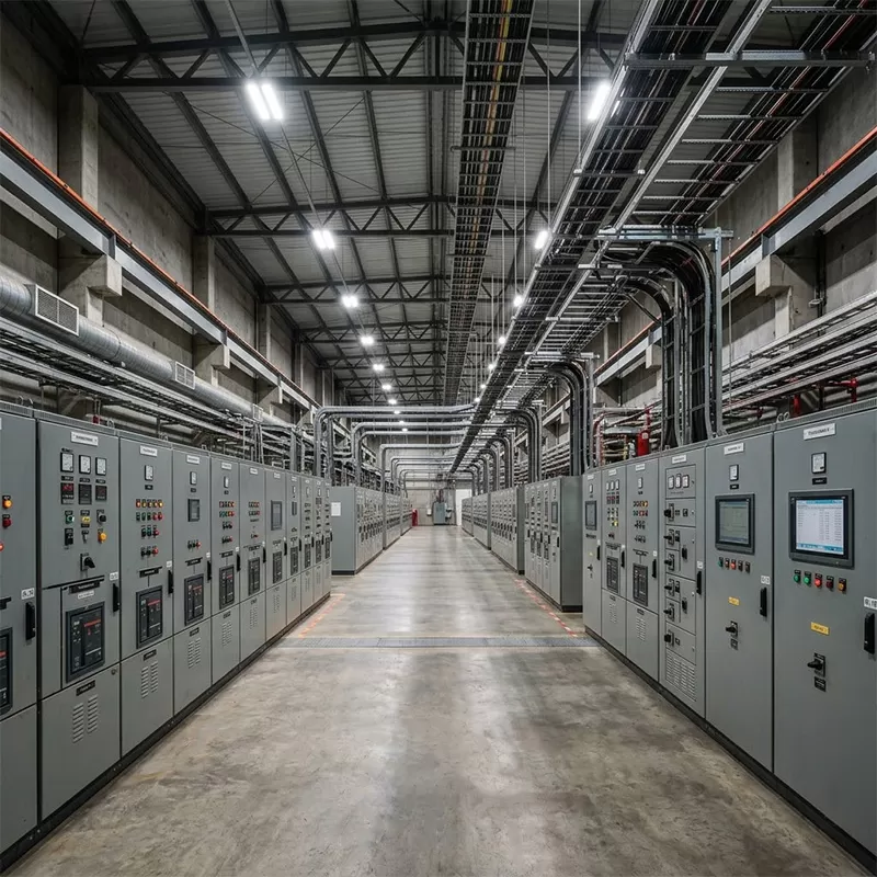
Industrial Lifecycle Value and Operational Continuity
Viewing electrical switchgear merely as a capital expenditure obscures its impact on long-term operating expenses. In continuous manufacturing, an unscheduled stoppage caused by catastrophic switchboard failure costs orders of magnitude more than the initial equipment purchase price. Selecting robust components, comprehensive internal separation forms, and intelligent diagnostic interfaces safeguards operational continuity across decades of production cycles.
As manufacturing paradigms migrate toward flexible production lines and higher electrical automation densities, the primary power distribution system must accommodate capacity adjustments, harmonic challenges, and data infrastructure integration without requiring total replacement. Facilities that invest in structured engineering, validated type testing, and proactive maintenance frameworks establish resilient foundations for uninterrupted industrial automation.
Frequently Asked Questions
Q1: What is the primary operational difference between a standard distribution panel and an industrial mains board?
A1: A standard distribution panel typically handles lower current thresholds, features minimal internal separation (usually Form 1 or Form 2), and serves light commercial or sub-distribution loads with basic thermal-magnetic protection. In contrast, an industrial mains board is engineered for primary utility or transformer incomers, handles substantially higher prospective fault levels (often 50kA to 100kA for 1 to 3 seconds), incorporates sophisticated internal separation (Forms 3b to 4b) to protect personnel during maintenance, and integrates advanced power quality monitoring, motorized circuit protection, and industrial communication protocols for automation environments.
Q2: Why is the Form 4b internal separation standard critical in automated manufacturing?
A2: Form 4b provides complete physical isolation of the main busbars from functional units, functional units from each other, and all external cable terminations from adjacent units. In high-uptime automated facilities, this architecture allows technicians to safely service, reconfigure, or pull out a faulted motor branch or feeder without shutting down the entire facility. It also halts the spread of internal arcing faults, ensuring an electrical failure within one starter module does not contaminate or compromise adjacent operational circuits.
Q3: How do non-linear automation loads affect mains board thermal design?
A3: Modern industrial equipment uses heavy concentrations of non-linear loads, such as VFDs, servo controllers, robotics power supplies, and induction heating systems. These generate high harmonic currents (particularly the 3rd, 5th, and 7th orders). Harmonics cause additional eddy current and skin-effect losses inside busbars, induce stray eddy currents in enclosure metalwork, and cause extreme current loading on the neutral conductor. Consequently, system designs require neutral busbars upsized to 200%, increased spacing between phase conductors, specialized de-rating of standard switchgear ratings, or active harmonic cancellation systems to prevent severe overheating.
Q4: What parameters dictate whether a low-voltage switchboard requires forced ventilation or closed-loop cooling?
A4: The decision depends on the internal power dissipation (total thermal wattage generated by breakers, busbars, and monitoring equipment), the maximum permissible internal operating temperature, the ambient external room temperature, and the required environmental IP rating. If the enclosure must be sealed to IP54 or higher to keep out fine industrial dust, moisture, or chemical vapors, natural convective heat dissipation is extremely low. If internal heat generation causes temperatures to exceed the rated operational limits of switchgear components (typically 40°C to 50°C), closed-loop industrial air conditioners or air-to-water heat exchangers are mandatory to keep internal temperatures within design tolerances without introducing external contaminants.
Q5: How does selective coordination (discrimination) prevent widespread manufacturing downtime?
A5: Selective coordination is the systematic arrangement of upstream and downstream protective devices to ensure that during an overcurrent, short circuit, or ground fault condition, only the protective device immediately upstream of the fault opens. The remainder of the distribution system remains fully energized. In automated manufacturing, lack of coordination means a short circuit on a minor secondary machine branch could trip the main circuit breaker within the incoming switchgear, entirely de-energizing the manufacturing line, shutting down pneumatic and cooling systems, and causing widespread inventory scrap and reset delays.
For custom engineering consultations, type-tested low-voltage switchgear layouts, and specialized distribution assemblies designed for automated plant environments, submit technical specifications to the electrical infrastructure engineering team at XDEPE: yoyo@xdepe.com.



 Cabinet (1).webp "Automatic Transfer Switch (ATS) Failure: 5 Common Causes and How to Fix Them")
.webp "How to Select the Right 3 Phase Panel Board for Heavy Manufacturing Equipment")
 Switchgear (1).webp "What is a Withdrawable (Drawer-Type) Switchgear? A Complete Beginner's Guide")
.webp "Main Distribution Board vs. Sub Main Distribution Board: What's the Difference & How to Choose?")
