
Automated manufacturing environments operate on razor-thin tolerances where electrical reliability directly determines throughput, equipment longevity, and plant safety. Modern production lines integrate multi-axis robotics, continuous process control systems, variable frequency drives (VFDs), and dense servo arrays. Within these high-demand infrastructures, selecting and configuring an industrial-grade 3 phase db box forms the cornerstone of operational stability. Sub-distribution systems can no longer be treated as static junction points; they serve as dynamic protection, isolation, and monitoring hubs engineered to withstand fluctuating thermal profiles, electromagnetic interference, and severe short-circuit stresses.
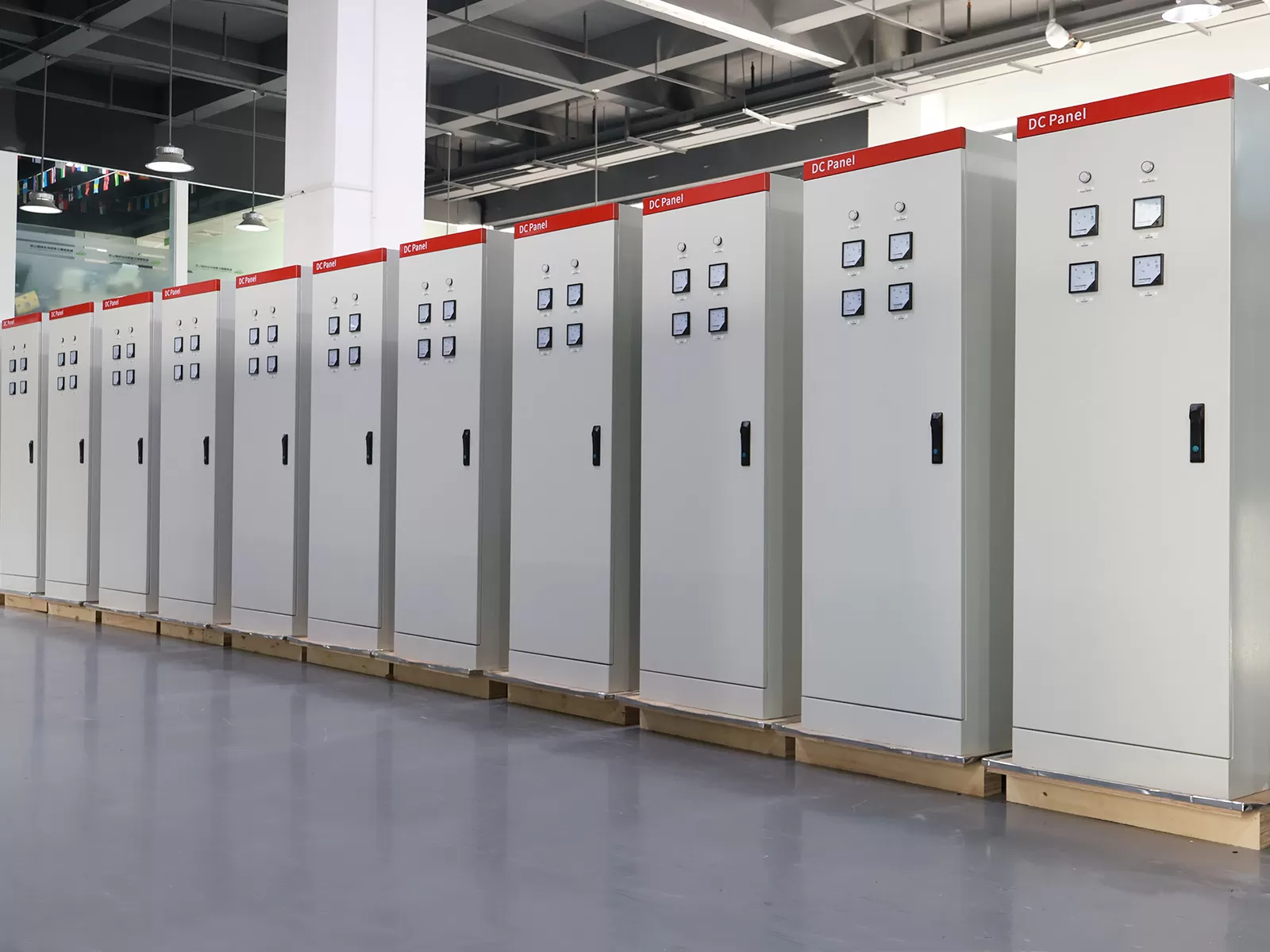
.webp?t=1791959200008 "3 phase db box")
Architectural Anatomy of Industrial Sub-Distribution Systems
Low-voltage distribution within automated manufacturing plants must bridge the transition from central switchgear to sensitive machine-level control panels. The internal architecture of a distribution assembly determines how effectively it segregates faults, dissipates heat, and facilitates maintenance without forcing unplanned line shutdowns.
Busbar Topologies and Dynamic Fault Ratings
Electrolytic tough pitch (ETP) copper busbars provide the primary conduit for current distribution across three-phase branches. In an industrial environment characterized by high prospective fault currents, busbar design must account for electrodynamic forces generated during short-circuit transients. When a phase-to-phase fault occurs, peak currents produce electromagnetic forces that can deflect, warp, or tear unreinforced conductors from their mountings.
- Rated short-time withstand current (Icw) metrics dictate the busbar's thermal survival across a calibrated duration, typically one second.
- Rated peak withstand current (Ipk) measures the dynamic mechanical resistance against immediate magnetic repulsion during the first sub-transient peak.
- Busbar clearances, creepage distances, and dielectric insulation barriers must comply strictly with pollution degree 3 conditions common to factory environments containing airborne particulates and humidity.
- Comb-type and stepped busbar configurations optimize conductor density while maintaining required surface-to-air ratios for convective cooling.
Internal Separation Forms (IEC 61439-2)
The standard IEC 61439-2 defines modular boundary separation within switchgear and controlgear assemblies. In automated facilities, internal segregation protects maintenance technicians from accidental contact with live adjacent circuits while localized troubleshooting takes place.
- Form 2b provides segregation between the centralized busbars and all functional units, preventing dropped tools or wiring slippage from causing catastrophic bus faults.
- Form 3b introduces physical separation between individual functional output units, ensuring that a terminal flashover on one machine drive branch does not propagate to adjacent control loops.
- Form 4b maximizes continuous uptime by completely isolating functional units, their termination points, and the incoming busbar assembly from one another, enabling hot-swap replacements and targeted maintenance.
Thermal and Mechanical Sizing of the 3 Phase DB Box Under Nonlinear Industrial Loads
Modern electrical automation introduces significant nonlinear loads into three-phase systems. Switched-mode power supplies, programmable logic controllers (PLCs), high-frequency induction heaters, and six-pulse or twelve-pulse inverter drives distort sinusoidal current waveforms, generating harmonic currents that fundamentally alter thermal dissipation within the enclosure.
Managing Harmonic Distortion and Neutral Loading
Third-order (180 Hz) and related triplen harmonics do not cancel out in the neutral conductor of a three-phase system. Instead, these currents add arithmetically in the neutral path, frequently generating neutral currents that exceed phase conductor loading by 130% to 170%. Under these operating conditions, undersized enclosures and standard neutral assemblies quickly overheat, leading to dielectric breakdown and unprovoked thermal trips.
- Double-sized (200%) neutral busbar options mitigate triplen harmonic heating in high-density automated testing and assembly zones.
- K-rated distribution transformers and detuned line reactors positioned upstream alleviate excessive harmonic distortion prior to terminal sub-distribution.
- Continuous monitoring of Total Harmonic Distortion for Current (THDi) at the distribution board ensures nonlinear distortions remain within acceptable IEEE 519 operating thresholds.
Thermal De-rating Inside Enclosures
Heat dissipation within an unventilated IP-rated enclosure relies primarily on radiative and conductive heat transfer through the cabinet walls. When multiple miniature circuit breakers (MCBs) or molded case circuit breakers (MCCBs) operate continuously at elevated capacity, localized internal ambient temperatures can rise far above factory ambient levels.
- Circuit breaker thermal de-rating tables must be calculated using internal enclosure temperatures (often 50°C to 55°C) rather than external ambient references (typically 25°C to 30°C).
- Grouping factors dictate that when more than six protective devices are mounted side-by-side on a DIN rail, continuous rated current capabilities drop by up to 20% due to mutual thermal radiation.
- Enclosure surface area calculations must verify that the heat dissipation coefficient (measured in W/m²·K) balances aggregate internal watt loss under peak production duty cycles.
Enclosure Metallurgy and Environmental Ingress Standards
Industrial machinery faces aggressive environmental challenges, ranging from cutting fluid mists and washdown chemicals to mechanical impact from autonomous mobile robots (AMRs) and forklift traffic. The enclosure envelope must protect sensitive switchgear against both gradual atmospheric corrosion and acute physical trauma.
Material Selection Parameters
Cold-rolled mild sheet steel coated with electrostatic polyester powder paint provides dependable structural rigidity for controlled, dry industrial environments. Sheet thickness should maintain a minimum of 1.2 mm to 1.5 mm to resist torsional deflection under heavy conduit loading.
For chemical manufacturing, pharmaceutical cleanrooms, and food-processing washdown zones, AISI 304 or AISI 316L stainless steel enclosures are mandatory. Stainless steel delivers exceptional passivation against chlorine-based cleaning agents and organic acids, preventing galvanic deterioration at fastener penetrations and gland plate interfaces. Glass-reinforced polyester (GRP) and polycarbonate enclosures offer specialized alternatives where complete electrical insulation and non-magnetic construction are strictly required.
Ingress Protection and Impact Resistance
Enclosure protection ratings must align with the target operational zone:
- IP54 provides standard dust protection and splashing water resistance, suitable for localized workshops and clean assembly bays.
- IP65 and IP66 enclosures incorporate closed-cell continuous polyurethane (PUR) gaskets, delivering absolute dust-tight seals capable of repelling high-pressure industrial washdown jets.
- IK08 to IK10 impact ratings ensure the housing resists kinetic impacts up to 20 Joules, safeguarding internal switchgear against accidental mechanical collisions common to dynamic production floors.
Circuit Protection Coordination and System Selectivity
Downtime in automated manufacturing rapidly cascades into substantial economic loss. Electrical faults must be contained strictly to the affected sub-circuit without tripping upstream protective devices, a discipline known as cascading selectivity.
Total Versus Partial Discrimination
Selectivity requires careful coordination between upstream MCCBs or air circuit breakers (ACBs) and downstream branch circuit breakers. In the event of a branch short circuit, only the protective device immediately upstream of the fault should clear the circuit, leaving the rest of the distribution board fully operational.
- Current-based discrimination leverages differing tripping thresholds, functioning effectively when prospective fault currents are moderate.
- Time-graded discrimination introduces intentional, milliseconds-long delays in upstream trip units, allowing downstream devices to clear faults before upstream trips initiate.
- Energy-based discrimination assesses the peak let-through energy (I²t) of downstream current-limiting breakers, ensuring the upstream unit’s unlatching threshold is never reached during transient events.
Residual Current and Transient Voltage Suppression
Variable frequency drives introduce high-frequency leakage currents to ground through motor cable shielding and internal filter capacitors. Standard Type A or Type AC residual current devices (RCDs) will either blind or nuisance-trip under these conditions. Industrial automation lines require Type B or Type B+ RCDs, which detect high-frequency AC and smooth DC residual currents up to 100 kHz.
Type 1 and Type 2 Surge Protective Devices (SPDs) installed directly on incoming phase busbars protect sensitive PLC input/output modules from switching surges caused by large inductive motor loads and inductive kickback from emergency shutoff contactors.
Procurement Specifications and Engineering Customization
Procuring distribution equipment for automated manufacturing requires cross-functional alignment between electrical design engineers, plant maintenance staff, and sourcing managers. Standard catalog assemblies rarely satisfy the nuanced demands of complex industrial installations.
Customization requirements frequently focus on cable entry configurations, internal mounting spatial depth, and neutral-to-earth busbar topology. OEMs often collaborate with engineering teams at XDEPE to tailor mounting pan dimensions, neutral bus sizing, and specialized knockouts to accommodate high-density armored cabling and specialized industrial busbar trunking taps.
- Specify segregated terminal chambers to separate incoming primary mains cables from outgoing automation wiring looms, reducing cross-talk and streamlining thermal dissipation.
- Require transparent, flame-retardant poly-carbonate phase barriers across all uninsulated live parts to facilitate infrared thermographic scanning without exposing operators to live arc-flash hazards.
- Incorporate dedicated DIN-rail space reserves of 25% to 30% to accommodate future automation cells, safety relays, and smart IoT telemetry hardware.
- Verify that neutral and ground busbars match phase distribution capacity point-for-point to maintain structural balance during multi-phase line-to-neutral imbalances.
Field Installation, Commissioning, and Smart Automation Integration
Commissioning an industrial power distribution board requires rigorous testing protocols before energization. Errors in torque application, phase identification, or insulation clearance can cause severe arc faults upon initial switch-on.
Pre-Commissioning Verification Protocols
Installation teams must conduct comprehensive quality assessments using calibrated testing apparatus:
- Torque-verification across all mechanical screw clamps, split washers, and bolted busbar joints using calibrated torque wrenches to eliminate high-resistance thermal hotspots.
- Insulation resistance (megohmmeter) testing at 1000V DC between phases, and between phases and ground, confirming readings well in excess of statutory minimums (typically >100 MΩ).
- Phase sequence and rotation verification to prevent three-phase induction motors from running in reverse rotation upon commissioning, which could destroy mechanical gear assemblies and pump impellers.
- Dielectric withstand testing (high-potential test) to identify microscopic cracks or dielectric contamination on internal support insulators.
During the design and construction phases of complex industrial cells, system builders rely on technical reviews by XDEPE to cross-verify prospective fault levels against dynamic thermal dissipation metrics, preventing costly field retrofits during startup.
Digitalization and SCADA Connectivity
Industry 4.0 paradigms demand continuous diagnostic visibility across every level of the electrical network. When standardizing a 3 phase db box across high-throughput assembly lines, integrating smart power meters and networked circuit breakers transforms conventional distribution into an intelligent diagnostic asset.
- RS-485 Modbus RTU and industrial Ethernet protocols (EtherNet/IP, PROFINET) stream voltage, current, power factor, and harmonic metrics directly to the plant SCADA or manufacturing execution system (MES).
- Embedded microswitches and auxiliary contacts transmit real-time circuit breaker status (open, closed, tripped on fault) to supervisory alarms.
- Non-intrusive current transducers (CTs) mounted per branch circuit track
phase balance continuously, flagging failing motor bearings or failing heating
elements before an actual short circuit occurs.
Preventive Maintenance and Lifecycle Optimization
Maintaining long-term operational resilience demands systematic inspection regimes. Electrical equipment subjected to cyclic loading, continuous vibration, and environmental contamination degrades predictably if left unmanaged.
Infrared thermography remains the primary non-destructive maintenance tool for distribution boards. Annual or bi-annual thermographic scans performed under full production load identify micro-ohmic contact resistance increases across lug terminations, switch contacts, and busbar fishplates before thermal stress triggers an arc event.
When developing plant-wide preventive maintenance schedules, consulting equipment specialists such as XDEPE ensures that diagnostic criteria align with hardware stress limits. Routine maintenance schedules must prioritize vacuum-based particulate cleaning rather than compressed air blowouts, which inadvertently drive conductive metallic dust into breaker trip mechanisms and delicate electronic sub-assemblies.
Frequently Asked Questions
Q1: Why is a dedicated 3 phase db box preferred over multiple
single-phase boards in manufacturing facilities?
A1: Three-phase
sub-distribution provides structural electrical balance across the utility
supply, reduces conductor cross-section requirements for equivalent power
transmission, and supplies the necessary rotating magnetic field required by
industrial induction motors and three-phase automated equipment. Managing loads
through a centralized three-phase board also enables coordinated selective
protection, lower copper losses, and centralized SCADA telemetry.
Q2: How does harmonic current generated by variable speed drives
affect neutral conductor sizing?
A2: Drives, rectifiers, and
switched-mode automation power supplies draw non-sinusoidal currents rich in odd
triplen harmonics (3rd, 9th, 15th). These harmonic currents do not cancel at the
neutral point; instead, they add arithmetically. In high-density automation
environments, neutral currents can exceed 150% of the individual phase currents.
Consequently, neutral conductors and busbars within the distribution board must
be sized at 200% of the phase conductor rating to prevent catastrophic
overheating.
Q3: What criteria determine whether an industrial distribution
assembly requires an IP54 or IP65 rating?
A3: The choice depends
entirely on the operating environment. An IP54 enclosure provides protection
against basic dust deposits and light splashing, which is sufficient for dry,
climate-controlled automation panels. If the assembly is situated in an
environment exposed to high-pressure washdown chemicals, heavy cutting oil
atomization, or fine conductive carbon/metallic dust, an IP65 or IP66 rating
with closed-cell polyurethane gaskets and compression latches is necessary to
prevent dielectric breakdown.
Q4: What is the mechanical difference between rated short-time
withstand current (Icw) and peak withstand current (Ipk)?
A4: Icw
defines the root-mean-square (RMS) short-circuit current the busbar assembly can
carry for a specified time (such as 1 second) without sustaining thermal
degradation or insulation damage. Ipk represents the absolute instantaneous peak
current the busbar geometry and mechanical bracing can withstand during the
initial asymmetric fault peak without suffering irreversible mechanical
deformation caused by electromagnetic forces.
Q5: Can standard Type AC residual current devices be deployed in
automated machinery distribution circuits?
A5: Standard Type AC RCDs
are not suitable for circuits containing variable frequency drives, servo
drives, or complex electronic power supplies. These nonlinear loads generate
high-frequency residual currents and smooth DC leakage components that blind
Type AC sensors, rendering them incapable of tripping during a genuine fault.
Industrial automation boards require Type B or Type B+ RCDs designed to sense
both AC and DC earth leakage currents across a wide frequency spectrum.
Engineering Consultation and Technical Inquiries
A well-engineered 3 phase db box protects capital-intensive machinery while maintaining energy efficiency, reducing operational disruptions, and safeguarding field personnel. Designing electrical sub-distribution networks that align with rigorous IEC standards requires balancing thermal dynamics, fault-level calculations, harmonic mitigation, and field-level installation ergonomics.
To discuss project specifications, custom enclosure configurations, or technical integration requirements for automated manufacturing lines, connect directly with the technical application engineering team at XDEPE:
Email: yoyo@xdepe.com
Technical Support Portal:
support.xdepe.com




 Cabinet (1).webp "Automatic Transfer Switch (ATS) Failure: 5 Common Causes and How to Fix Them")
.webp "How to Select the Right 3 Phase Panel Board for Heavy Manufacturing Equipment")
 Switchgear (1).webp "What is a Withdrawable (Drawer-Type) Switchgear? A Complete Beginner's Guide")
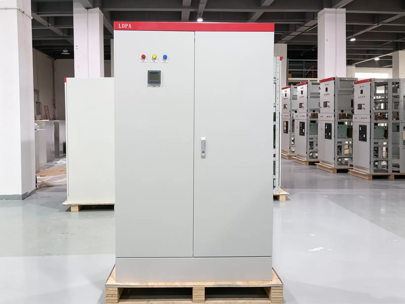
.webp "Main Distribution Board vs. Sub Main Distribution Board: What's the Difference & How to Choose?")
