
Planning an automation upgrade or designing a new robotic assembly line? Request a technical consultation with XDEPE today to review your load schedules, thermal models, and panel footprints with our application engineering team before freezing your procurement specifications.
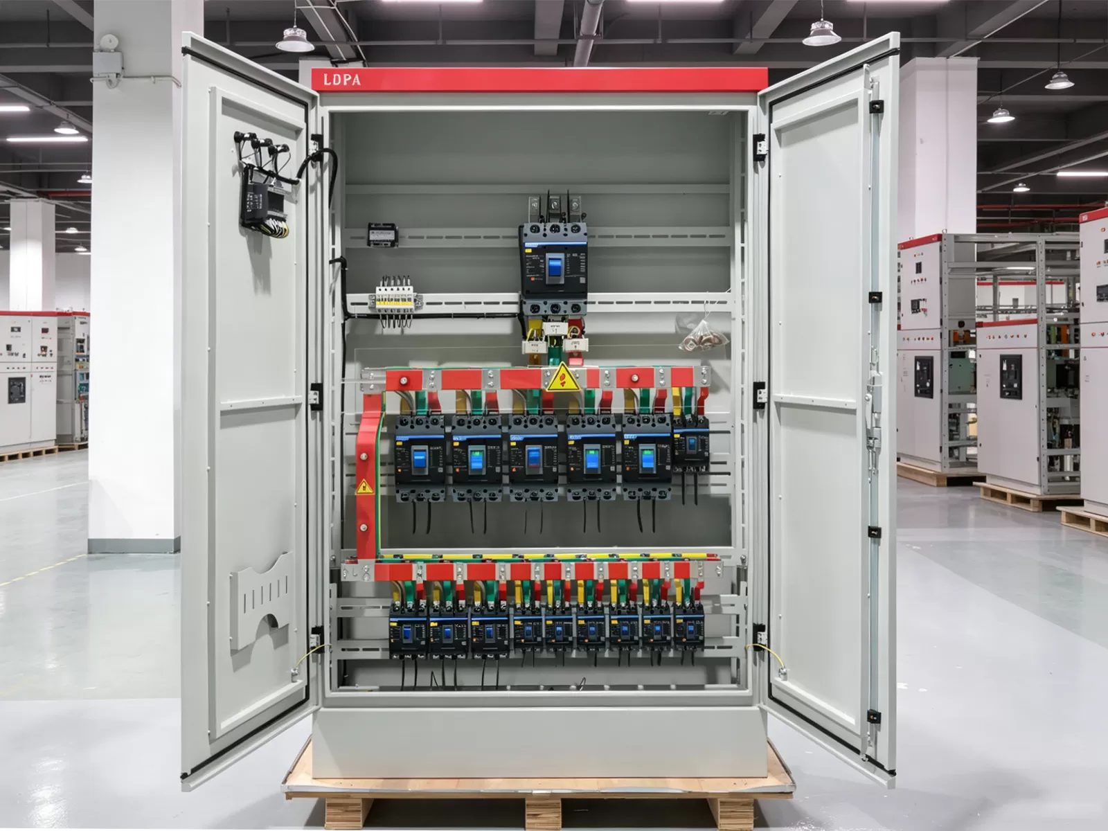
Modern Industrial Automation Demands a New Power Architecture
Industrial machinery has fundamentally changed over the past decade. Conveyors and stamping presses once ran on simple across-the-line induction motors with predictable inductive loads. Today, automated facilities rely on high-speed delta robots, multi-axis servo systems, linear motors, machine vision rigs, and variable frequency drives (VFDs).
These dynamic systems create non-linear load profiles. They generate substantial harmonic currents and draw rapid acceleration spikes within milliseconds. Standard commercial panels cannot handle these operational stresses.
Specifying a modern 3 phase distribution board requires looking beyond raw kilowatt ratings. Engineers must assess short-circuit withstand values, total harmonic distortion mitigation, thermal density within compact footprints, and native digital connectivity.
A power distribution failure in a modern lights-out plant halts the entire value stream. Downstream components starve within seconds. Choosing the correct 3 phase distribution board is therefore not just an electrical compliance task; it is a critical operational availability decision.
Load Calculation and Dynamic Capacity Sizing
Accounting for Non-Linear and Cyclic Duty Loads
Sizing an industrial panel for automation requires deep analysis of operational profiles. Servo packs and high-performance drives cycle from zero to maximum torque in fractions of a second. Simply summing the nameplate full-load amps (FLA) leads to either nuisance tripping or massive over-engineering.
Calculate your base continuous load by assessing the root-mean-square (RMS) current rather than peak thermal values. Follow this baseline calculation sequence:
- Identify baseline continuous loads running 100% of the shift (chillers, control power supplies, cabinet blowers).
- Calculate the thermal equivalent current ($I_{rms}$) for intermittent cyclic drives using cycle times, acceleration ramps, and dwell durations.
- Add locked-rotor or transient inrush draws for direct-on-line ancillary motors to confirm the main busbar does not drop below voltage thresholds during line starts.
Future Expansion Margin
Production lines frequently retool. Automation engineers frequently add inspection stations, robotic transfer arms, or barcode tracking scanners months after commissioning. Never specify a 3 phase distribution board at more than 70% to 75% of its rated busbar capacity during initial deployment.
Reserve at least 25% physical module space on the DIN rails and chassis plate. This prevents retrofitting outboard sub-panels when the plant adds extra tooling.
Fault Levels and Withstand Ratings
Verify the prospective short-circuit current (PSCC) at the panel input. Automated cells situated close to primary distribution transformers regularly face prospective fault levels exceeding 35kA or 50kA.
Your specification must call out two distinct ratings under IEC 61439-2:
- Rated Ultimate Short-Circuit Breaking Capacity ($I_{cu}$): The absolute maximum fault current the main protective device can clear safely.
- Rated Service Short-Circuit Breaking Capacity ($I_{cs}$): The fault level the device can clear while remaining fully functional without replacement. Insist on $I_{cs} = 100\% I_{cu}$ for continuous-process automation.
- Rated Short-Time Withstand Current ($I_{cw}$): Crucial for the incoming busbar assembly to ensure internal copper busbars physically withstand electromagnetic forces during a downstream fault until protective devices trip.
Power Quality, Protection, and Harmonics Management
Managing Triplen Harmonics on the Neutral Bus
Variable frequency drives without front-end active filters and switched-mode power supplies (SMPS) pull current in narrow pulses. This non-sinusoidal switching generates harmonic distortion, specifically the 3rd, 9th, and 15th orders (triplen harmonics).
Triplen harmonics do not cancel out in the neutral conductor of a three-phase system. Instead, they add up arithmetically. In high-density automation lines, neutral current can exceed the phase currents.
When engineering an automation-grade 3 phase distribution board, specify an oversized neutral busbar rated for 200% of the phase busbar capacity. This prevents neutral bus overheating, conductor insulation degradation, and nuisance fires.
Coordinated Surge Protection Devices (SPDs)
Industrial environments switch inductive loads constantly. Large contactors, welding rigs, and cranes dump extreme transient voltage spikes onto the distribution bus. Fragile programmable logic controllers (PLCs), optical sensors, and network switches operate on the same secondary system.
Implement a coordinated multi-stage surge protection strategy inside the panel:
- Type 1 SPD: Located at the primary service entrance to clamp massive lightning transients and external utility switching events.
- Type 2 SPD: Installed directly inside the automation 3 phase distribution board to suppress residual internal inductive surges below 1.5kV.
- Status Telemetry: Specify SPDs equipped with integrated microswitches connected directly to the digital inputs of your safety PLC or building management network for immediate failure alarming.
Breaker Selection: Trip Curves and Discrimination
Automation environments cause frequent false trips if breaker curves are misapplied. Standard Type B trip curves (3-5 times rated current) fail reliably around automation machinery.
Use Type C curves (5-10 times rated current) for general control circuits, cooling pumps, and cabinet illumination. Use Type D curves (10-20 times rated current) for sub-circuits feeding isolation transformers, high-inrush power supplies, and direct drives. Ensure total upstream-downstream selectivity to prevent a single branch short circuit from dropping the main breaker.
Smart and Connected Distribution Boards
Static distribution hardware is obsolete in high-yield manufacturing. Production supervisors demand detailed per-station power metrics and early warnings long before an overcurrent trip shuts down assembly operations.
Forward-thinking manufacturers like XDEPE design smart 3 phase distribution board solutions that embed edge micro-sensors directly into the circuit breaker chassis. These integrated architectures measure voltage, phase angle, active power, reactive power, and harmonic spectrum up to the 31st order.
Predictive Maintenance Through Thermal Telemetry
Loose terminations, copper oxidation, and sustained phase imbalances cause progressive thermal rises. If left undetected, they result in catastrophic electrical flashovers. Integrate non-contact infrared thermal sensors or wireless surface acoustic wave (SAW) temperature tags onto primary copper busbar joints and breaker incoming lugs.
These sensors feed real-time heat maps to machine control software. If terminal temperature rises 10°C above baseline under steady load, the automated control system alerts maintenance staff to inspect the torque settings during the next planned changeover.
Fieldbus Protocol Integration
A smart panel must communicate via native industrial communication protocols rather than isolated proprietary interfaces. Specify that internal energy meters and intelligent trip units communicate directly via:
- Modbus TCP/IP for straightforward supervisory control and data acquisition (SCADA) integration.
- Profinet or EtherCAT for direct real-time communication with machine line PLCs.
- OPC UA for secure data transport straight to MES platforms without passing
through intermediate gateways.
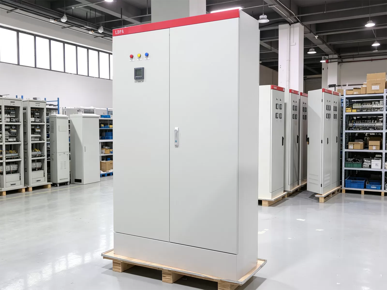
Physical Enclosure Specifications, Ingress Protection, and Thermal Design
Ingress Protection (IP) Ratings
Machining environments generate fine metal shavings, oil aerosols, and coolant vapors. Cleanroom and food packaging installations feature pressurized washdowns. The enclosure rating of your 3 phase distribution board must match these external conditions.
| Application Environment | Required Protection Rating | Enclosure Construction Material |
|---|---|---|
| Clean electronics assembly / dry pharmaceutical | IP54 / NEMA 12 | Cold-rolled mild steel with powder coating |
| General automotive assembly & metalworking | IP55 to IP65 / NEMA 4 | 1.5mm to 2.0mm mild steel or 304 stainless steel |
| Food, beverage, sanitary washdown | IP66 or IP69K / NEMA 4X | 316L stainless steel, sloped-top, orbital welds |
Active Thermal Dissipation
Miniaturization creates massive internal heat loads. Dense clusters of power electronics, DC switch-mode supplies, and smart meters reject considerable thermal energy into sealed enclosures.
Calculate internal dissipation using standard thermodynamic conduction balance:
Required Cooling Capacity (W) = Internal Heat Dissipation (W) - (Surface Area x Enclosure Heat Transfer Coefficient x Temp Delta)
If the ambient plant floor regularly hits 35°C to 40°C, natural convection falls short. Specify side-mount closed-loop air conditioners with digital thermostats or air-to-water heat exchangers. Sealed systems maintain internal IP ratings while preventing external oily ambient air from blowing across sensitive micro-breakers.
Compliance, Safety, and International Standards
IEC 61439-1 & 2 vs. UL 508A
Global machinery deployments require strict adherence to international electrical assembly regulations. Avoid referencing outdated standards like IEC 60439.
Under IEC 61439-1 and 2, the distribution panel is classified as a Low-Voltage Switchgear and Controlgear Assembly. The standard replaces the vague concepts of "type-tested" and "partially type-tested" boards with mandatory design verification methods (testing, calculation, or physical design rules covering temperature rise, dielectric properties, and short-circuit withstand).
For installations heading to North America, specify compliance with UL 508A (Industrial Control Panels) and verify that the Short Circuit Current Rating (SCCR) matches the maximum available fault current calculated by the local utility service profile.
Internal Separation Forms
Internal barriers limit the propagation of arcs and prevent accidental human contact with live copper when working on adjacent circuits. Determine the separation form based on system criticality:
- Form 2b: Busbars are separated from the functional units (breakers). Common for medium-duty commercial and non-critical manufacturing.
- Form 3b: Busbars are separated from functional units, and functional units are separated from each other. Terminations remain shared.
- Form 4b: The standard for advanced automation. Busbars are separated from functional units, all functional units are individually compartmentalized, and incoming/outgoing cable termination points are completely isolated from each other. This allows technicians to terminate a new automation branch without de-energizing the main incoming supply.
Step-by-Step Specification Checklist for Engineers
Use this technical framework when compiling procurement sheets for your next 3 phase distribution board:
- Incoming Service Parameters: System voltage (e.g., 400V/480V 3-phase, 4-wire + Ground), frequency (50/60Hz), prospective fault current ($I_{cu}$ / SCCR).
- Busbar Sizing: Electrolytic copper (Cu-ETP), tin-plated or silver-plated; minimum 200% neutral sizing for high-harmonic branches.
- Protection Coordination: Main incoming air circuit breaker (ACB) or molded case breaker (MCCB) with electronic trip unit; branch miniature circuit breakers (MCBs) matched to dynamic load curves (Type C/D).
- Form of Separation: Form 3b minimum; Form 4b preferred for zero-downtime manufacturing lines.
- Physical Construction: Minimum 1.5mm sheet steel enclosure, continuous polyurethane door gasket, 3-point locking system, custom paint/stainless grade, and IP rating.
- Thermal Strategy: Total watt-loss heat calculations, forced ventilation vs. closed-loop active refrigeration.
- Smart Integration: Modbus TCP/IP, Profinet, or EtherCAT multi-channel power meters; continuous busbar infrared or contact thermal sensors.
Frequently Asked Questions
Q1: How does an automation-grade 3 phase distribution board differ from a standard commercial building panel?
A1: Commercial building panels primarily serve static, linear loads like resistive heating, office computing, and baseline illumination. An automation-grade board manages dynamic, high-inrush motor loads, complex harmonic spectrums from variable speed drives, and frequent switching surges. Automation boards also feature heavier fault withstand capacities ($I_{cw}$), isolated separation barriers (up to Form 4b), active thermal management, and direct integration into machine-level fieldbus control networks.
Q2: Why does our automation line experience neutral busbar overheating even when phase loads appear balanced?
A2: This condition stems from triplen harmonics (predominantly the 3rd, 9th, and 15th harmonic orders) produced by three-phase variable frequency drives, DC power supplies, and servo systems. While fundamental 50Hz or 60Hz balanced currents cancel out in the neutral conductor, triplen harmonic currents add up constructively on the neutral line. In facilities with heavy non-linear loads, neutral currents can register at 130% to 180% of phase currents, requiring a 200% neutral busbar to prevent thermal damage.
Q3: What internal separation form is most cost-effective for robotic manufacturing cells?
A3: Form 3b or Form 4b is the baseline recommendation. Form 4b isolates busbars, functional breaker units, and external cable terminations into individual shielded metal compartments. While it carries a higher initial fabrication cost, it allows maintenance technicians to safely route and terminate new wiring for robotic sub-assemblies while the primary busbar remains live. This prevents costly facility-wide blackouts during small retooling projects.
Q4: How should we determine breaker trip curves when feeding banks of servo drives?
A4: Never use Type B trip curves for servo drives or inductive loads due to instantaneous magnetic trips caused by transient charging currents. Type C curves work for small, standalone drives with integrated soft-charging circuits. However, dynamic multi-axis systems and isolation transformers draw substantial inrush currents during line stabilization. Specifying Type D curves or electronic trip MCCBs with adjustable short-time pickup delays ($I^2t$) prevents nuisance tripping during rapid machine acceleration.
Q5: Can existing traditional panels be retrofitted to meet 2026 digital monitoring standards?
A5: Yes. You can upgrade legacy panels by installing split-core current transformers (CTs) or Rogowski coils around existing phase busbars and conductor drops without pulling apart the copper structure. Pair these sensors with compact DIN-rail edge power meters and magnetic surface temperature probes. These retrofit kits transmit telemetry over industrial Ethernet protocols to your central SCADA system, delivering comprehensive condition-based monitoring without complete panel replacement.
Secure Your Line Reliability with Advanced Power Distribution
Every minute of unplanned line stoppage erodes manufacturing margins. Specifying an industrial 3 phase distribution board requires balancing electrical safety, structural integrity, thermal mechanics, and digital observability. Modern automated factories cannot operate on legacy electrical infrastructure.
At XDEPE, we engineer tailored industrial power distribution platforms built strictly to IEC 61439-2 and UL 508A requirements. Whether you require custom Form 4b compartmentalization, active harmonic mitigation, or full Profinet edge telemetry, our specialized applications team can review your single-line diagrams.
Contact the engineering team at XDEPE today to request a full specification review, submit your project electrical single-line diagrams, or receive a fast-turnaround commercial quotation for your upcoming automation build.




 Cabinet (1).webp "Automatic Transfer Switch (ATS) Failure: 5 Common Causes and How to Fix Them")
.webp "How to Select the Right 3 Phase Panel Board for Heavy Manufacturing Equipment")
 Switchgear (1).webp "What is a Withdrawable (Drawer-Type) Switchgear? A Complete Beginner's Guide")
.webp "Main Distribution Board vs. Sub Main Distribution Board: What's the Difference & How to Choose?")
