
Automated manufacturing systems, high-speed robotics, and continuous processing facilities demand an uninterrupted, pristine power supply. Modern operational environments cannot tolerate transient voltage drops, unplanned tripping, or excessive thermal losses. At the heart of this operational reliability sits the low-voltage electrical distribution panel board, serving as the central nervous system that bridges incoming high-capacity utility feeds with precision-engineered automation hardware. Selecting, engineering, and deploying these power distribution centers requires an exacting approach rooted in electro-dynamic calculations, thermodynamic optimization, and international standards compliance.
Industrial facilities are increasingly dominated by non-linear loads, servo drives, variable frequency controllers, and sensitive industrial automation equipment. This shift has rewritten the baseline requirements for low-voltage power architecture. A secondary switchboard is no longer simply a mechanical enclosure carrying copper conductors and thermal-magnetic circuit breakers. Instead, it operates as an active, monitorable node within industrial Internet of Things (IIoT) ecosystems, demanding deterministic fault clearing, arc mitigation, and precise mechanical isolation to safeguard both process uptime and human personnel.
.webp?t=1790231492081 "electrical distribution panel board")
Structural Architecture and Internal Segregation Standards
Internal mechanical layout dictates how effectively a distribution enclosure handles thermal build-up, dynamic short-circuit stresses, and routine maintenance without requiring total facility shutdowns. Specifying the correct Form of Separation under standard IEC 61439-2 defines the physical boundaries between functional units, busbars, and termination points.
Form 1 and Form 2: Basic configurations where busbars are either open to functional units or segregated merely from the terminal blocks. Suitable primarily for commercial footprints or non-critical secondary lighting systems, these setups expose maintenance personnel to energized main busbars during localized component servicing.
Form 3a and Form 3b: Physical separation of the main busbar from functional units, with individual separation of functional units from one another. Form 3b extends this separation by isolating the terminals for external conductors from the functional units, though not necessarily from each other. This level of segregation is commonly applied in light manufacturing and auxiliary support systems.
Form 4a and Form 4b: The benchmark configuration for high-reliability manufacturing equipment, chemical processing, and mission-critical production. Busbars are isolated from functional units, functional units are isolated from each other, and all cable termination assemblies are completely separated into dedicated compartments. Form 4b provides independent termination compartments for every outgoing circuit, enabling technical personnel to pull, dress, and terminate new cable runs alongside live, operating circuits safely.
Design teams partnering with XDEPE often configure Form 4b modular chassis systems for high-density production lines. This compartmentalized layout mitigates cascading physical damage from localized component degradation, preventing an electrical fault in a lower-tier motor feeder from migrating to the primary incoming switchboard sections.
Thermal Dynamics, Ingress Ratings, and Busbar Geometry
Internal heat generation represents the single greatest threat to continuous service life within high-current enclosures. Joule heating ($I^2R$ losses) across contact resistance interfaces, main distribution bars, and magnetic trip units within densely packed modular assemblies accelerates conductor insulation breakdown if ventilation strategies are inadequately calculated.
Electrodynamic Force and Busbar Sizing
During a prospective short-circuit event, electrodynamic forces between adjacent parallel copper busbars reach peak stresses proportional to the square of the peak fault current ($I_p^2$). The engineering calculation must account for the rated short-time withstand current ($I_{cw}$) for a duration of typically 1.0 or 3.0 seconds, alongside the peak withstand current ($I_{pk}$). Busbar supports must be manufactured from high-grade, glass-reinforced thermoset polyester or polyamide compounds capable of resisting mechanical shear under violent electro-magnetic repulsion without cracking or tracking.
Thermal Dissipation vs. Ingress Protection (IP) Balance
Achieving a high Ingress Protection rating (such as IP54, IP55, or IP65) inherently restricts natural convective airflow, trapping heat inside the metallic envelope. High-draw manufacturing machinery produces ambient internal temperatures that easily exceed standard design baselines of 35°C to 40°C. When specifying an electrical distribution panel board for harsh foundry, packaging, or wet-wash processing conditions, engineers must calculate the total heat dissipation using IEC TR 60890 methodologies.
Skin Effect and Busbar Profiles: Solid rectangular busbars experience current crowding toward the conductor edges when alternating current passes through large cross-sections. Employing laminated, parallel conductor arrays or specially profiled hollow conductors optimizes skin depth utilization, reducing raw copper tonnage while lowering thermal resistance.
Surface Finishing: Tin-plating, silver-plating, or specialized matte coatings at joint junctions diminish galvanic oxidation and optimize joint emissivity, substantially dropping operational junction temperatures compared to bare copper.
Climate Control Integration: When mechanical air filtration (louvers with washable synthetic media) fails to hold internal temperatures within the thermal-derating envelope of sensitive electronic trip units, closed-loop industrial air conditioners, heat-pipe exchangers, or vortex coolers must be structurally calculated into the total enclosure load.
Overcoming Electrical Challenges in Modern Automated Facilities
Deploying automated machinery introduces specific electrical stress profiles that conventional building distribution grids rarely encounter. Variable frequency drives (VFDs), computerized numerical controls (CNC), robotic servo racks, and high-frequency induction units inject severe electrical pollution back into the distribution network.
Mitigating Harmonics and Neutral Loading
Non-linear loads generate 3rd, 5th, 7th, 11th, and higher-order harmonic currents. Triplen harmonics (specifically the 3rd and 9th orders) do not cancel out in the neutral conductor of a three-phase system; instead, they add up algebraically. In modern automated plants, neutral conductor currents can exceed the phase currents by up to 130% to 170%. Failure to specify double-sized (200%) neutral busbars leads directly to catastrophic neutral overheating, high neutral-to-ground voltages, and erratic microprocessor reboots in sensitive programmable logic controllers (PLCs).
Active harmonic filters (AHF) and passive low-pass detuned filter banks must be integrated immediately downstream of the incoming main circuit breaker. Positioning dynamic harmonic compensation within the secondary distribution architecture neutralizes distortion at the source, preventing upstream transformer core saturation and maintaining the total harmonic distortion of voltage ($THD_V$) under the 5% threshold defined by IEEE 519 standards.
Selective Coordination and Cascading Protection
Unintended tripping of upstream protective devices shuts down entire assembly cells, yielding massive losses in throughput and work-in-progress materials. Achieving complete selective coordination requires total selectivity between downstream Miniature Circuit Breakers (MCB) or Molded Case Circuit Breakers (MCCB) and upstream Air Circuit Breakers (ACB) across the entire prospective fault current spectrum—from overload ranges down to the instantaneous, short-circuit breaking capacity ($I_{cu}$).
Time-current curves (TCC) must be mapped during the engineering phase, utilizing advanced electronic trip units equipped with adjustable Long-time ($L$), Short-time ($S$), Instantaneous ($I$), and Ground-fault ($G$) parameters. Zone Selective Interlocking (ZSI) enables communication between cascading breakers via hardwired digital signaling or communication protocols. If a fault occurs on an outgoing automation line, the immediate downstream breaker signals the upstream feeder to momentarily delay its trip sequence, isolating the localized branch without dropping the entire electrical distribution panel board.
Smart Infrastructure Integration: IIoT and Telemetry Convergence
The convergence of power distribution hardware and manufacturing execution systems (MES) transforms switchgear from a passive failsafe into an intelligent monitoring hub. Modern equipment incorporates smart sensors, edge computing nodes, and standardized communication buses natively within the structure.
Continuous thermal imaging via non-contact infrared sensors or wireless surface acoustic wave (SAW) temperature probes on critical busbar joints detects localized resistance increases months before a connection degrades into an arc flash event. Furthermore, integrating multi-channel power quality meters capable of capture rates exceeding 512 samples per cycle enables real-time voltage sag, swell, and transient tracking.
Using industrial communication protocols—such as Modbus TCP/IP, Profinet, and EtherNet/IP—the internal devices transmit operational health metrics directly to the plant-wide SCADA framework. Advanced system integrators leverage the manufacturing flexibility of XDEPE to construct custom telemetry channels, ensuring automated isolation of malfunctioning feeder lines before hardware failures stall primary processing conveyors.
Procurement and Engineering Evaluation Criteria
Procuring industrial-grade electrical assemblies demands rigorous verification against internationally recognized standards, avoiding configurations based purely on surface-level nameplate ratings. Engineering teams and procurement managers should evaluate potential switchboard builds against the following systematic criteria:
Type-Tested Verification (IEC 61439-1/-2): Ensure the manufacturer provides certified test laboratory verification for all 13 design verifications. These include temperature-rise limits, dielectric properties, short-circuit withstand capability, protection circuit effectiveness, clearances and creepage distances, and mechanical operation. Assemblies certified merely by derivation or incomplete extrapolation present non-quantifiable operational risks.
Internal Arc Fault Containment: Arc flash incidents generate pressures exceeding several tons per square meter alongside temperatures exceeding 19,000°C. Enclosures tested in accordance with IEC TR 61641 or IEEE C37.20.7 criteria contain internal arc explosions via specialized top-mounted pressure relief flaps, arc-resistant internal baffling, and optical arc detection systems coupled with ultra-fast pyrotechnic arc-quenching devices capable of extinguishing faults within 4 milliseconds.
Sheet Metal Construction and Coating System: Heavy-duty manufacturing environments require structural integrity built on cold-rolled steel or electro-galvanized sheet metal with a thickness of no less than 2.0 mm for load-bearing frameworks and 1.5 mm for doors and covers. High-adhesion electrostatic polyester powder coatings, tested for 500 to 1,000 hours of salt spray exposure (ASTM B117), are essential to resist industrial corrosion, caustic vapors, and chemical cleaning agents.
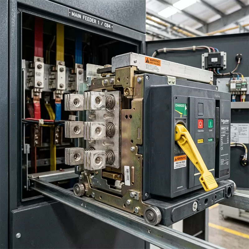
Maintainability and Future Scalability: Fully modular chassis systems allow field modifications without the need for hot-work metal drilling or cutting inside the enclosure. Standardized vertical bus dropper spacing, pre-punched mounting plates, and plug-in or fully withdrawable cassette-type circuit breakers dramatically lower Mean Time to Repair (MTTR) while preserving future expansion capacity of 20% to 30% available DIN rail and module volume.
Commissioning, Deployment, and Predictive Maintenance Procedures
Proper field deployment of an electrical distribution panel board bridges theoretical design with decades of reliable duty. Once the enclosure arrives on-site, rigorous testing sequences must precede energization.
The mechanical deployment begins with leveling and anchoring the plinth base to a structurally reinforced concrete pad or switchgear trench. Conduits and armored cables entering from either top or bottom must pass through gland plates with IP-rated cable glands to preserve the enclosure integrity against dust and moisture ingress. Once conductors are dressed, all factory-made and field-made bolted busbar connections must be re-torqued using calibrated digital torque wrenches, matching torque specifications designated by the component manufacturers, and marked with torque seal lacquer.
Pre-commissioning electrical testing requires a battery of precise measurements:
Insulation Resistance Testing: Using a high-voltage megohmmeter applied at 1,000V DC between phases, between phases and neutral, and between phases and ground. Minimum acceptable resistance values must exceed 100 Megohms, establishing the absolute integrity of the internal dielectric barriers.
Contact Resistance (Ductor) Testing: Micro-ohmmeter testing across primary ACB and MCCB contacts and critical busbar splices identifies loose, oxidized, or mechanically compromised bolted connections before high current flows through them.
Secondary Injection Testing: Electronic trip units must be verified using secondary current injection test kits, confirming that pick-up currents and time delay parameters correlate precisely with the facility's engineered coordination study.
In operational phases, predictive condition-based maintenance outmodes calendar-based switchgear shutdowns. Utilizing ultrasound diagnostics to listen for partial discharge within dry insulation cavities, coupled with semi-annual thermal imaging audits of line-side terminals, gives maintenance technicians advanced visibility into impending hardware degradation. Incorporating these diagnostic pathways into initial manufacturing specifications, supported by the precision engineering capabilities of XDEPE, ensures predictable lifecycle costs, minimized downtime, and superior operational longevity.
Frequently Asked Questions
Q1: What is the primary difference between an electrical distribution panel board and a motor control center (MCC)?
An electrical distribution panel board focuses fundamentally on dividing incoming electrical power into multiple branch circuits, providing overcurrent and short-circuit protection for downstream sub-panels, lighting, computing systems, and machinery. A Motor Control Center (MCC) is specifically dedicated to the control, sequencing, and operational protection of electric motors. An MCC integrates localized motor starters, variable frequency drives, soft starters, contactors, and dedicated overload relays within individual withdrawable buckets, whereas a general distribution board primarily houses protection devices such as ACBs, MCCBs, and surge suppression systems.
Q2: Why is Form 4b internal separation preferred for continuous automated manufacturing operations?
Form 4b separation isolates the main busbars from the functional units, isolates all functional units from one another, and provides completely independent compartments for all outgoing terminal connections. In a continuous manufacturing process, taking down an entire switchboard to inspect, maintain, or add a single branch circuit costs tens of thousands of dollars per hour in lost production. Form 4b allows maintenance technicians to access, cable, and terminate a specific circuit safely without exposing themselves to energized busbars or neighboring live functional units, maximizing personnel safety and eliminating facility-wide outages.
Q3: How does non-linear loading affect the sizing of internal neutral busbars?
Non-linear loads such as variable frequency drives, switching power supplies, and automated robotic systems create harmonic distortions, specifically triplen harmonics (3rd, 9th, 15th orders). These harmonic currents do not cancel each other in the neutral conductor of a three-phase system; instead, they add constructively in the neutral path. Under heavy harmonic conditions, neutral current can exceed the phase currents by up to 170%. Consequently, neutral busbars must be engineered at 200% of the cross-sectional area of the phase conductors to prevent extreme thermal failure and voltage instability across the network.
Q4: What role does the short-time withstand current ($I_{cw}$) play in secondary distribution reliability?
The rated short-time withstand current ($I_{cw}$) indicates the maximum short-circuit current that a switchboard assembly can carry for a defined duration (typically 1.0 or 3.0 seconds) without suffering structural, mechanical, or thermal damage. A high $I_{cw}$ rating ensures that the distribution assembly can withstand extreme electrodynamic forces while waiting for upstream, time-delayed selective breakers to clear a downstream fault. Without a sufficient $I_{cw}$ rating, intense magnetic repulsion forces can physically deform busbars, crack bus supports, and trigger widespread internal flashovers before the protection devices can isolate the fault.
Q5: How can facilities control internal moisture and condensation inside an IP65-rated distribution enclosure?
High Ingress Protection enclosures (such as IP65) seal out external moisture, but they also trap humidity present inside the cabinet during installation or maintenance. When external ambient temperatures drop rapidly, the internal air hits its dew point, causing immediate condensation across cold metal surfaces and live electrical components. To combat this, enclosures should be fitted with anti-condensation space heaters controlled by electronic hygrostats and thermostats. Maintaining the internal enclosure temperature a few degrees above the external ambient temperature keeps air above its dew point, successfully eliminating internal moisture formation.
Optimize Your Industrial Power Distribution Architecture
Engineering robust, standards-compliant power infrastructure requires precision design, rigorous thermal validation, and flawless mechanical fabrication. Connect with the senior engineering and system integration team at XDEPE to review your facility's electrical distribution specifications, streamline switchgear design, and deploy high-reliability low-voltage solutions customized for demanding industrial automation environments.
Direct Engineering Inquiries: yoyo@xdepe.com




 Cabinet (1).webp "Automatic Transfer Switch (ATS) Failure: 5 Common Causes and How to Fix Them")
.webp "How to Select the Right 3 Phase Panel Board for Heavy Manufacturing Equipment")
 Switchgear (1).webp "What is a Withdrawable (Drawer-Type) Switchgear? A Complete Beginner's Guide")
.webp "Main Distribution Board vs. Sub Main Distribution Board: What's the Difference & How to Choose?")
