
Industrial production environments demand uncompromising electrical reliability. Automated assembly cells, multi-axis computer numerical control (CNC) machinery, high-throughput packaging lines, and robotics all depend on stable multi-phase power distribution. Within these high-demand infrastructures, the 3 phase board acts as the central point of control, bridging upstream medium-voltage sub-stations with sophisticated downstream production machinery. As automation complexity intensifies, the engineering requirements governing these low-voltage assemblies have evolved far beyond basic circuit containment.
Modern electrical engineers and plant infrastructure directors face distinct design challenges. Non-linear loads introduce destructive harmonics into local distribution networks. High-density motor control architectures generate substantial thermal stress within switchgear enclosures. Rapid load fluctuations risk nuisance tripping or undervoltage faults that disrupt synchronous automation processes. Meeting these challenges requires an in-depth understanding of enclosure dynamics, fault level containment, thermal mitigation, and switchgear coordination.
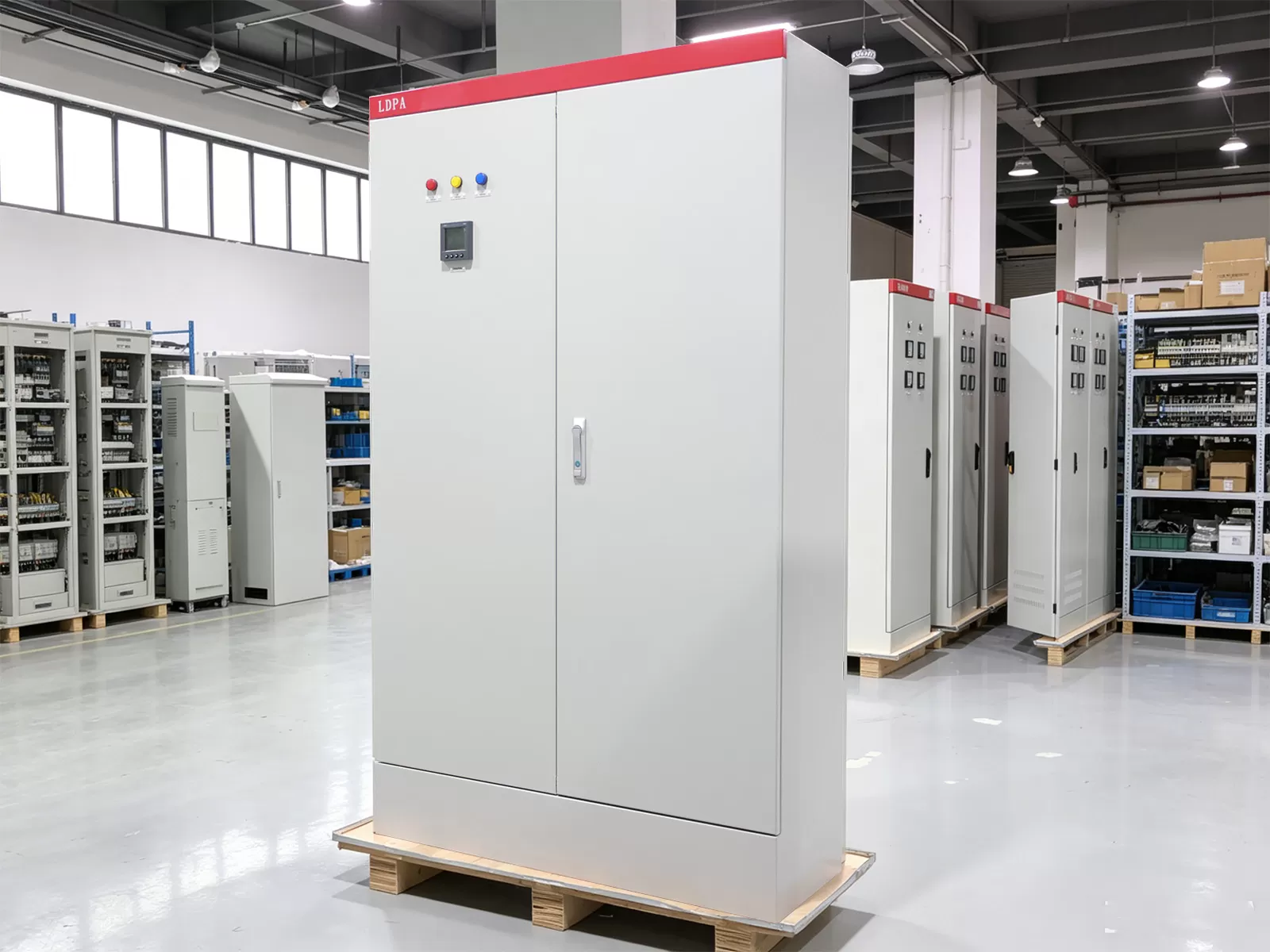
Structural Topology and Electrical Architecture
At its core, three-phase distribution utilizes alternating currents carried through three conductors, offset in phase angle by 120 electrical degrees. This configuration delivers constant power transfer and optimal conductor efficiency compared to single-phase equivalents. In an automation facility, distributing this balanced power requires a 3 phase board designed to withstand both continuous operational stresses and severe transient fault conditions.
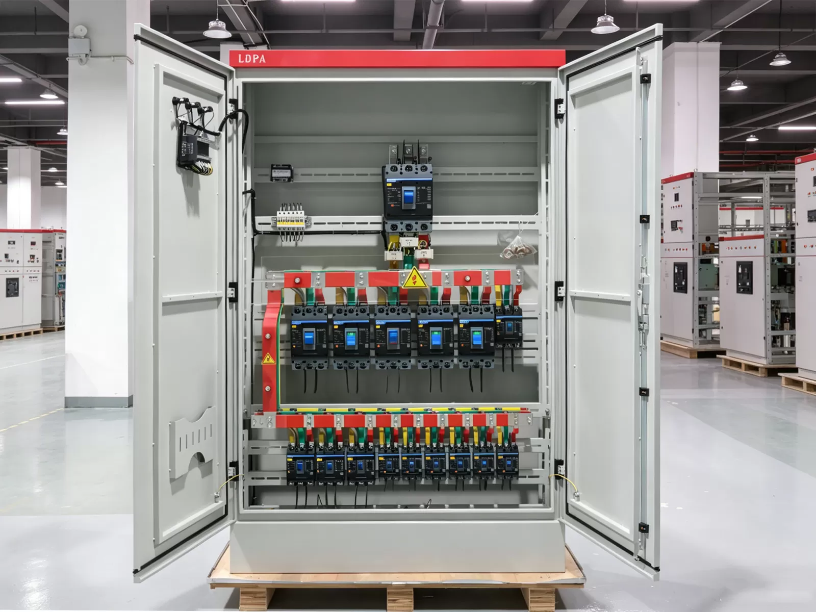
The internal architecture centers on the busbar assembly. High-conductivity electrolytic copper (Cu-ETP) forms the primary conductor array, sized specifically to carry rated operational current without exceeding standardized temperature rise limits. Electrical engineers evaluate busbars through both continuous current capacity and short-circuit withstand performance. Under short-circuit conditions, electromagnetic forces can exert tons of mechanical stress per meter of busbar, demanding robust mechanical bracing with track-resistant, glass-reinforced polyester insulators.
Internal Separation and Form Classification
Plant safety and operational continuity depend heavily on the internal segmentation of the assembly. International standards, particularly the IEC 61439 series, classify low-voltage assemblies into specific forms of internal separation ranging from Form 1 through Form 4b:
- Form 1 provides no internal separation between busbars, functional units, and terminals. This configuration is virtually absent in critical automation environments due to fault propagation risks.
- Form 2 separates busbars from functional units, providing a foundational baseline for non-critical secondary distribution.
- Form 3 isolates busbars from functional units while separating functional units from each other, though outgoing terminal connections remain grouped.
- Form 4 isolates busbars from functional units, functional units from each other, and isolates all outgoing terminal connections. Within high-tier industrial automation, Form 4b configurations allow maintenance teams to work on discrete automation circuits without isolating adjacent, running production lines.
Fault Level Coordination and Short-Circuit Withstand
Industrial manufacturing plants operating near high-capacity utility transformers exhibit elevated prospective short-circuit currents. A robust switchgear assembly must possess verified ratings for rated short-time withstand current ($I_{cw}$) and rated peak withstand current ($I_{pk}$). These values dictate the assembly's ability to survive magnetic repulsion forces and thermal energy surges during an uncleared fault downstream.
Downstream protection devices must provide coordinated selectivity. Upstream air circuit breakers (ACBs) or high-capacity molded case circuit breakers (MCCBs) must remain passive during localized equipment faults, allowing branch miniature circuit breakers (MCBs) or motor protection circuit breakers (MPCBs) to isolate specific machine anomalies. Incorrect cascading or poor energy-let-through management can trigger main breaker trips, shutting down entire plant wings.
Integration Challenges with Heavy Automation Equipment
Automated manufacturing introduces continuous non-linear electrical profiles. Variable frequency drives (VFDs), servo drives, induction welders, and switch-mode DC power supplies draw current in pulses rather than smooth sinusoidal curves. This behavior produces harmonic distortions, primarily the 5th, 7th, 11th, and 13th orders, along with triplen harmonics that accumulate on neutral conductors.
These current harmonics cause skin-effect phenomena in internal copper busbars, artificially elevating conductor resistance and generating unexpected internal heat. Neutral busbars, historically specified at half the cross-sectional area of phase bars in legacy lighting panels, must frequently be rated at 100% or 200% of the phase conductor capacity in modern automated manufacturing facilities. Failure to adjust for these harmonic currents leads to premature insulation degradation, localized melting, and erratic control relay performance.
Inductive inrush currents present another operational hurdle. Large three-phase induction motors utilized in hydraulic presses, high-capacity blowers, and conveyance systems can draw locked-rotor currents between six and eight times their full-load rating during direct-on-line start-up. Even when soft-starters or VFDs are utilized, rapid cyclical machine cycles can trigger localized voltage drops. A precisely configured 3 phase board incorporates low-impedance bus structures and transient voltage surge suppression (TVSS/SPD) modules directly across the primary bus to protect sensitive programmable logic controllers (PLCs) against line-side voltage sags and transients.
Thermal Dynamics and Environmental Protection in Hostile Plants
Electrical gear installed directly on factory floors encounters adverse environmental factors including airborne metal shavings, cutting fluid aerosols, ambient humidity, and ambient temperature spikes. Designing the switchgear requires balancing ingress protection against heat dissipation capacity.
Ingress Protection (IP) ratings such as IP54, IP55, or IP65 seal electrical compartments from particulates and liquids. However, sealing an enclosure traps heat generated by MCCB internal resistances, metering transformers, and termination contact resistance. In high-density installations, internal temperatures can easily exceed the 40°C calibration baseline of standard thermal-magnetic trip units, triggering nuisance tripping without an actual overcurrent condition.
Engineers solve this challenge through multiple thermodynamic and structural approaches:
- De-rating calculations applied to circuit protective devices based on the highest expected ambient temperatures inside the cabinet envelope.
- Computational Fluid Dynamics (CFD) airflow modeling to position higher-dissipation components at the upper elevations of the enclosure, matched with louvered filter fans or closed-loop air-to-air heat exchangers.
- Surface-treated copper busbars with matte black heat-shrink or specialized coatings to improve radiation heat transfer compared to bright bare copper.
- Implementation of phase separation barriers that double as directed convection chimneys, ensuring unforced airflow over high-amperage terminals.
For specialized installations requiring complex thermal and structural balancing, engineering teams work with custom panel manufacturing partners like XDEPE to optimize physical layout configurations, calculate accurate temperature-rise limits, and ensure long-term structural resilience.
Procurement and Engineering Specification Matrix
Specifying low-voltage switchgear for international projects requires navigating regional electrical codes, operational duty cycles, and integration requirements. Procurement teams and engineering consultants must evaluate prospective assemblies against standardized functional parameters rather than superficial exterior dimensions.
| Technical Parameter | Standard Industrial Baseline | Advanced Automation Requirement | Engineering Implication |
|---|---|---|---|
| Operational Voltage ($U_e$) | 400V / 415V AC | Up to 690V AC | Dictates dielectric clearance and creepage distances across busbar supports. |
| Insulation Voltage ($U_i$) | 690V | 1000V | Protects against transient switching overvoltages and line spikes. |
| Short-Time Withstand ($I_{cw}$) | 25kA / 1s | 50kA to 65kA / 1s | Determines mechanical support spacing and structural frame gauge requirements. |
| Enclosure Ingress (IP) | IP31 / IP42 | IP54 to IP65 | Protects sensitive electronic components from washdown, particulates, and moisture. |
| Segregation Architecture | Form 2b | Form 4b Type 7 | Permits live maintenance on isolated modules while adjacent production runs safely. |
| Busbar Material | Electrolytic Tough Pitch (Cu-ETP) | Tin-plated or Silver-plated Cu | Prevents oxidation at bolted joint interfaces and ensures low surface contact resistance. |
Beyond electrical metrics, long-term procurement decisions must factor in component modularity. Modular chassis designs permit rapid reconfiguration when assembly lines expand or production equipment is repurposed. Utilizing standardized DIN-rail mounting sections, flexible droppers, and universal breaker carriage systems allows maintenance teams to adapt distribution circuits without re-drilling structural panel components or voiding enclosure safety ratings.
Installation Best Practices and Commissioning Protocols
The operational reliability of a high-performance switchgear assembly depends heavily on field installation and commissioning standards. Even the most robust factory-built switchboard will fail prematurely if subjected to improper mounting, mechanical stress, or inaccurate termination practices.
Enclosure placement requires perfectly level concrete plinths or steel channel bases. Misalignment induces torsional stress on the external frame, transferring mechanical shear forces into internal busbar connections and preventing smooth engagement of withdrawable circuit breakers. Cable entry management is equally critical: when routing high-amperage single-core cables through metallic gland plates, non-magnetic materials like aluminum or brass must be used to eliminate eddy currents that cause localized inductive heating around the enclosure entry zone.
A rigorous commissioning routine involves systematic testing steps before energization:
- Torque Verification: Every bolted busbar splice and breaker termination must be checked with calibrated torque wrenches according to manufacturer specifications. Markings with torque inspection paint prevent oversight and establish a visual maintenance baseline.
- Insulation Resistance (IR) Testing: Megohmmeter testing conducted at 500V or 1000V DC between phases, and between phases and ground, verifying that transit and storage conditions have not introduced moisture or particulate tracking across insulators.
- Contact Resistance Testing (Micro-Ohm Measurement): Digital low-resistance ohmmeter (DLRO) testing of primary busbar joints confirms that joint resistance falls within baseline tolerances, preventing hot-spot formation under load.
- Secondary Injection Testing: Protective relay units and electronic trip
devices on incoming MCCBs require simulated fault currents to verify pick-up
times, instantaneous trip thresholds, and ground fault safety
operations.
Maintenance Architecture, Diagnostics, and Lifecycle Value
Unplanned downtime in high-throughput manufacturing plants carries astronomical costs. Maintaining switchgear integrity has transitioned from reactive repair to data-driven predictive maintenance. Facilities incorporating continuous monitoring detect thermal anomalies, partial discharge, and insulation failure long before mechanical breakdown occurs.
Thermographic imaging remains an indispensable predictive tool. Regularly scheduled infrared surveys identify high-resistance terminations caused by thermal cycling relaxation, galvanic corrosion, or inadequate original torque. Infrared viewing windows fitted directly onto terminal enclosures enable technicians to inspect critical bus joints under full load conditions without breaking arc-containment barriers or exposing personnel to arc-flash hazards.
Modern production facilities increasingly rely on continuous operational monitoring. Embedding continuous temperature monitoring sensors directly onto high-stress busbar joints, incoming cable lugs, and neutral distribution bars provides real-time condition tracking via SCADA systems. When designing complex automation distribution networks, consulting with XDEPE enables engineering teams to incorporate intelligent power meters, harmonic monitoring hardware, and continuous thermal sensing into their electrical configurations.
Strategic deployment of a high-quality 3 phase board delivers long-term lifecycle savings. While the initial capital expenditure for Form 4 separation, plated copper busbars, and robust industrial switchgear is higher than light-commercial alternatives, the total cost of ownership tells a different story. Reduced thermal loss, the elimination of nuisance trips, enhanced personnel safety during modifications, and switchgear longevity reaching 25 to 30 years provide clear economic returns for capital-intensive industrial plants.
Frequently Asked Questions
Q1: How does a Form 4b assembly differ functionally from a Form 2 assembly in an automation facility?
A1: A Form 2 assembly separates the main busbars from the functional units (breakers, switches), but terminals for external cables are not isolated from each other. In contrast, a Form 4b assembly isolates busbars from functional units, functional units from each other, and all individual outgoing cable terminals from one another. In an automated plant, Form 4b construction allows technicians to work safely inside an isolated terminal compartment for one machine circuit while adjacent production lines remain fully energized and operational.
Q2: Why are non-linear loads a primary concern when sizing internal busbars?
A2: Non-linear loads such as variable frequency drives and automated robotics draw non-sinusoidal currents rich in harmonic frequencies. These higher-frequency currents cause skin effects and proximity effects, forcing current toward the outer perimeter of copper conductors and increasing their effective resistance. This generates significantly higher internal operating temperatures. Additionally, triplen harmonics accumulate on the neutral conductor, demanding fully rated or oversized neutral busbars to prevent overheating.
Q3: What methods effectively mitigate arc flash risks within low-voltage industrial distribution boards?
A3: Arc flash risks are reduced through a combination of engineering designs and protective technologies. Key methods include specifying high internal separation forms, utilizing maintenance switches with instantaneous trip settings (energy-reducing maintenance switches, or ERMS), installing optical arc detection relays that trigger main breaker shunt trips in milliseconds, and integrating external infrared inspection windows to eliminate the need for opening doors during live inspections.
Q4: How does enclosure IP rating affect breaker thermal de-rating?
A4: Higher IP ratings, such as IP55 or IP65, create a tightly sealed cabinet to protect against dust, oils, and moisture. However, this dramatically limits natural convection cooling. Trapped heat elevates the internal ambient temperature above standard breaker calibration points (typically 40°C). Consequently, circuit breakers must be de-rated to lower continuous current thresholds, or the enclosure must be engineered with integrated closed-loop air conditioners or heat exchangers to prevent nuisance tripping.
Q5: Under what operational conditions should an industrial plant upgrade from Form 2 to Form 4 segregation?
A5: Upgrading to Form 4 segregation is recommended when the cost of unscheduled downtime exceeds switchgear capital cost differentials. It is essential in continuous process automation, automotive assembly lines, cleanrooms, and facilities where safety policies prohibit working on or terminating cables near energized electrical hardware. Form 4 allows localized cabling and maintenance while the rest of the switchboard remains energized.
Engineered Solutions for Complex Automation Infrastructure
Selecting the optimal power distribution architecture requires balancing short-circuit withstand capabilities, environmental containment, harmonic mitigation, and long-term modular expansion. Precise alignment between mechanical architecture and electrical loads prevents costly plant stoppages, protects sensitive automation controllers, and ensures compliance with international electrical safety frameworks.
For custom switchgear development, industrial specification reviews, and specialized switchboard engineering for global automation projects, contact the engineering support specialists at XDEPE via yoyo@xdepe.com to evaluate your system design parameters.



 Cabinet (1).webp "Automatic Transfer Switch (ATS) Failure: 5 Common Causes and How to Fix Them")
.webp "How to Select the Right 3 Phase Panel Board for Heavy Manufacturing Equipment")
 Switchgear (1).webp "What is a Withdrawable (Drawer-Type) Switchgear? A Complete Beginner's Guide")
.webp "Main Distribution Board vs. Sub Main Distribution Board: What's the Difference & How to Choose?")
